
Calculus breaking and clearing attraction probe device with cohesively aligned laser fibers

An arrangement and probe technology, applied in the field of probes, can solve the problems of large striking surface, no heat and durability, and achieve the effects of large striking surface, long service life, and easy suction and removal.

Inactive Publication Date: 2014-08-13
叶向东
View PDF7 Cites 0 Cited by
  • Summary
  • Abstract
  • Description
  • Claims
  • Application Information

AI Technical Summary

Problems solved by technology

At present, there is no one that can be easily operated through endoscopic surgery, has excellent lithotripsy effect regardless of soft or hard stones, has a large impact surface, can control small stone fragments, quickly dissipates heat from the surgical field, quickly absorbs fragments without blocking, and does not generate heat for a long time Durable Ideal Stone Breaker

Method used


Image

  • Calculus breaking and clearing attraction probe device with cohesively aligned laser fibers
  • Calculus breaking and clearing attraction probe device with cohesively aligned laser fibers
  • Calculus breaking and clearing attraction probe device with cohesively aligned laser fibers

Examples


Embodiment 1

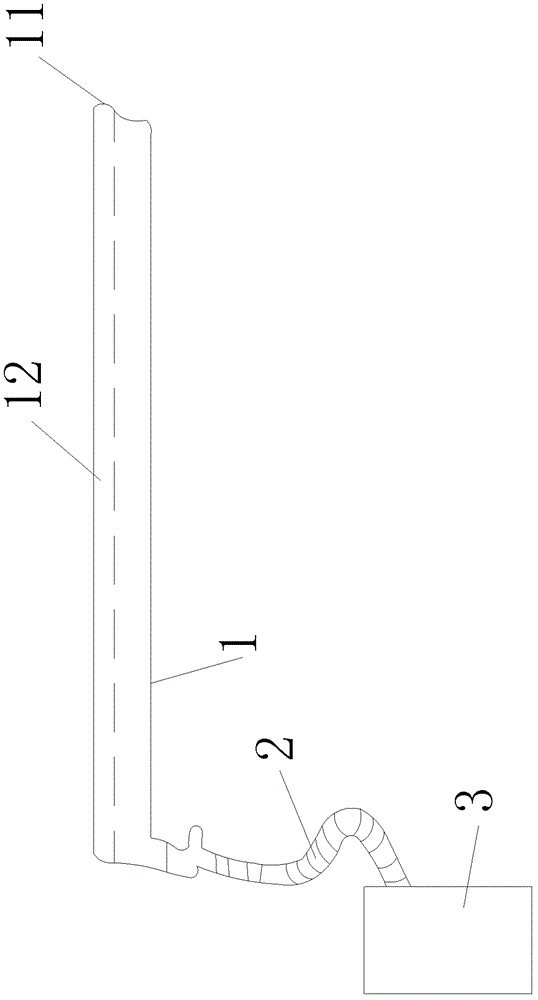
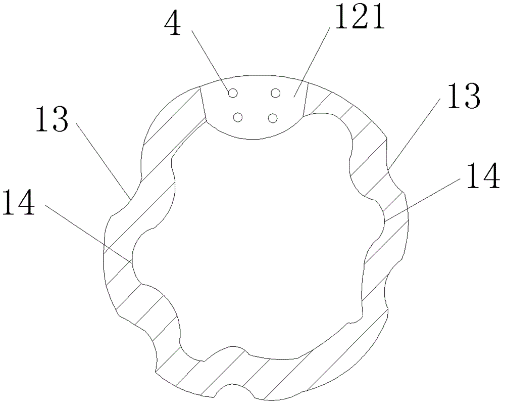
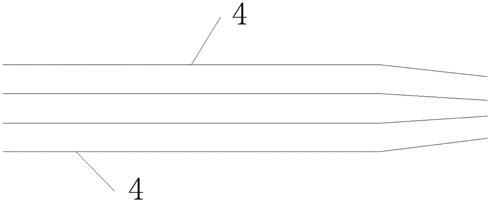
[0023] see Figure 1 to Figure 3 , a cohesive arrangement of laser optical fiber gravel removal probe rod device, which includes a hollow structure probe rod 1, the end of the hollow structure probe rod 1 is connected with a negative pressure suction device 3 through a connecting pipe 2, in the A protruding structure 11 is provided on the upper part of the front end of the hollow structure probe rod 1 . An optical fiber channel 12 that can accommodate at least two strands of laser optical fibers 4 is provided in the hollow structure probe rod 1, such as image 3 The laser fiber 4 is 4 strands, of course the laser fiber 4 also can be other numbers without affecting the scope of protection of the present invention, the fiber channel 12 has a cohesive optical fiber outlet 121 opened on the protruding structure 11 and has a cohesive fiber outlet 121 opened in The optical fiber inlet (not shown) at the end of the hollow structure probe rod 1 . The front ends of the laser fibers 4...

Embodiment 2

[0027] refer to Figure 4 to Figure 6 , the functions realized by this embodiment and Embodiment 1 remain the same, and the only difference is:

[0028] In the first embodiment, the outer surface groove 13 and the inner surface groove 14 of the hollow structure probe rod 1 make the hollow structure probe rod 1 actually be a grooved section probe rod 15, and in this embodiment, in addition to having In addition to the grooved section probe rod 15, there is also a non-slotted section probe rod 16. Specifically, the hollow structure probe rod 1 is composed of a grooved section probe rod 15 and a non-slotted section probe rod 16 arranged at the end of the grooved section probe rod 15; The outer surface of the section probe rod 15 is provided with at least one outer surface groove 13 along the length direction and at least one inner surface groove 14 is provided on the inner surface of the grooved section probe rod 15 along the length direction to form, the above-mentioned outer s...


PUM


Abstract

The invention discloses a calculus breaking and clearing attraction probe device with cohesively aligned laser fibers, comprising a hollow probe, wherein a tail end of the hollow probe is connected with a vacuum extractor through a connection pipe; a front end of the hollow probe is provided with a protruded structure on the upper part; and at least one fiber channel capable of containing at least two laser fibers is installed inside the hollow probe; the fiber channel is provided with a cohesive fiber outlet on the protruded structure and a fiber inlet on the tail end of the hollow probe; and front end of each laser fiber in the fiber channel is slightly bent to round up to be arranged on the cohesive fiber outlet to form a cohesive fiber calculus breaking and clearing structure, and the hollow probe is formed by a slotted probe and a slotless probe equipped at the end of the slotted probe. The device provided by the invention is featured by large calculus impact area, high calculus breaking efficiency, good calculus breaking effect regardless of hard or soft calculus and long service life, and is capable of rapidly breaking the calculus and removing broken pieces by absorbing.

Description

technical field [0001] The invention relates to a probe, and more specifically relates to a laser fiber cohesive arrangement type rubble-clearing stone-clearing probe rod device used for lithotripsy and removal of urinary calculi. Background technique [0002] Urinary calculus is a common and frequently-occurring disease in my country. Although the treatment of urinary stones at home and abroad has entered the era of minimally invasive surgery from open surgery, the high rate of residual stones after surgery is still a prominent problem in clinical work. [0003] At present, the existing pneumatic ballistic lithotripsy has a better effect, but it is a physical method. The large impact force has caused bleeding and it is difficult to control the size of the fragments. The stones bounce everywhere due to the large impact force and it is difficult to locate. Ultrasonic lithotripsy has certain effects, but it is almost useless for stones with relatively high hardness such as ca...

Claims


Application Information

Patent Timeline
Patent Type & Authority Patents(China)
IPC IPC(8): A61B18/26A61M1/00
Inventor 叶向东
Owner 叶向东
Learn More