Solvent oil-gas reclaiming device

A recovery device, oil and gas technology, applied in the direction of steam condensation, dispersed particle separation, chemical instruments and methods, etc., can solve the problems of low condensation recovery efficiency, high energy consumption, and influence on adsorption, and achieve high automation integration and superior electrical conductivity , the effect of investment saving

Inactive Publication Date: 2012-07-11
SUZHOU DA LING ENVIRONMENTAL TECH CO LTD
View PDF8 Cites 10 Cited by
  • Summary
  • Abstract
  • Description
  • Claims
  • Application Information

AI Technical Summary

Problems solved by technology

The condensation recovery efficiency of this method is low (less than 50%), regeneration and desorption is incomplete, which affects the recovery rate of solvent and the standard discharge of air
[0008] Since the above single process is difficult to meet environmental protection emission standards, solid usually adopts a combination of several processes, although the emission standards can be improved to varying degrees, but there are still some disadvantages to varying degrees
As disclosed in CN101259947 "gas station oil gas recovery device and its condensation adsorption integration method" and CN101402001 disclosed "oil gas recovery treatment device and condensation adsorption method thereof" both adopted the secondary condensation process and an integrated process method of an adsorber, An adsorber cannot guarantee the continuous work and operation of the entire device, that is, when the adsorbent in an adsorber reaches saturation, it cannot guarantee the adsorption work while desorbing
At the same time, there are disadvantages that the solvent cannot be completely desorbed and the adsorption material can be completely regenerated under the condition of low vacuum negative pressure.
Another example is CN102151414A disclosed "oil gas recovery device and adsorption and desorption switching device using condensation adsorption method". ice clogged passage
At the same time, due to the technical reasons of the dry vacuum pump itself, it is impossible to generate a high vacuum, so each regeneration and desorption is not complete, which will inevitably affect the adsorption of the next cycle, and even affect the recovery rate of the solvent and the standard discharge of air.

Method used


Image

  • Solvent oil-gas reclaiming device
  • Solvent oil-gas reclaiming device
  • Solvent oil-gas reclaiming device

Examples


Embodiment Construction

[0031] The present invention will be described in further detail below in conjunction with examples and specific implementation methods.

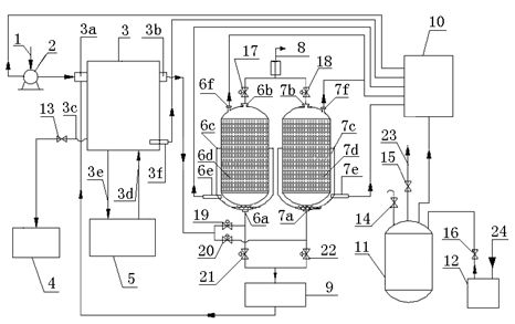
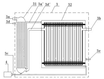
[0032] see figure 1 , a solvent oil gas recovery device, including fan 2, condensing part 3, solvent recovery tank 4, refrigerator 5, adsorption tanks 6 and 7, air discharge pipe 8 and vacuum pump 9, the inlet of fan 2 is connected to oil and gas source 1, and the outlet It communicates with the oil and gas inlet 3a of the condensing part, the oil and gas outlet 3b of the condensing part communicates with the oil and gas inlets 6a and 7a of the adsorption tank through pneumatic valves 19-22, and the solvent outlet 3c of the condensing part communicates with the solvent recovery tank 4 through the electric valve 13, and the refrigerant inlet of the condensing part 3d and the refrigerant outlet 3e of the condensing part are respectively communicated with the refrigerant machine 5, and the air discharge ports 6b and 7b of the adsorption tank a...


PUM


Abstract

The invention discloses a solvent oil-gas recovering device, wherein the oil-gas can be desorbed and recovered under a lower vacuum condition completely. The invention adopts an oil-gas isolation technology of combination of a traditional condenser and a jacket cooling metal wire net membrane filter, thereby realizing composite multistage condensation reclaiming; and meanwhile a heater is arranged outside the lower part of an absorption tank, and the heater is controlled by a micro computer to heat the absorption tank after an adsorbing material is saturated under on-line monitoring, so that the technical problems that a drying vacuum pump has a lower vacuum degree and the absorbing material is desorbed incompletely are solved effectively. The whole set of the device provided by the invention has a high atomization integration level, a saved investment, security and reliability; the recovering effect of the absorbing material is higher than 99%; the oil-gas reclaiming rate is more than 99%; and the gas emission pollutant can reach the national standard completely.

Description

technical field [0001] The invention relates to a solvent oil gas recovery device, in particular to a solvent oil gas recovery device in volatile chemical solvents. Background technique [0002] In many aspects of daily life and chemical production and storage, the volatilization and waste of chemical solvents such as oil and gas and the hidden safety hazards caused by them have always been difficult technical problems for people to solve, especially some flammable, explosive, toxic, low boiling point and volatile compounds. How to manage and recycle them at low cost, safely and efficiently, so as to save resources and benefit from safety and environmental protection has always been the desire of people. At present, the general methods for recycling such solvents at home and abroad are as follows: [0003] 1. Condensation recovery method. This method needs to use a large number of traditional condensers, and the equipment occupies a large area, requires a large investm...

Claims


Application Information

Patent Timeline
Patent Type & Authority Applications(China)
IPC IPC(8): B01D5/00B01D53/04
Inventor 陈兵刘道其刘刚李超前姚占东邓建军
Owner SUZHOU DA LING ENVIRONMENTAL TECH CO LTD
Why Eureka
Try Eureka