
Impeller cutting type vortex air floatation device

A cutting-type, air flotation technology, which is applied in the direction of flotation water/sewage treatment, etc., can solve the problems of wasting coagulation agent, large bubble diameter, and no gas volume adjustment device, so as to improve the efficiency of air flotation concentration, save treatment costs, The effect of saving power consumption

Inactive Publication Date: 2012-07-11
SOUTHEAST UNIV
View PDF7 Cites 5 Cited by
  • Summary
  • Abstract
  • Description
  • Claims
  • Application Information

AI Technical Summary

Problems solved by technology

However, since most of the impellers have several large air intake holes on each blade, the diameter of the generated air bubbles is relatively large, the air flotation effect is not ideal, and a large amount of coagulant will be wasted
The conventional vortex-concave air flotation technology is powered by a motor with a single speed. The most important thing is that there is no air volume adjustment device. It is difficult to adapt to the changes in the quality and volume of the sewage to be treated immediately. The phenomenon of insufficient or excessive air volume often occurs, and the air bubbles are large. Affect the effect of air flotation concentration

Method used


Image

  • Impeller cutting type vortex air floatation device
  • Impeller cutting type vortex air floatation device
  • Impeller cutting type vortex air floatation device

Examples


Embodiment Construction

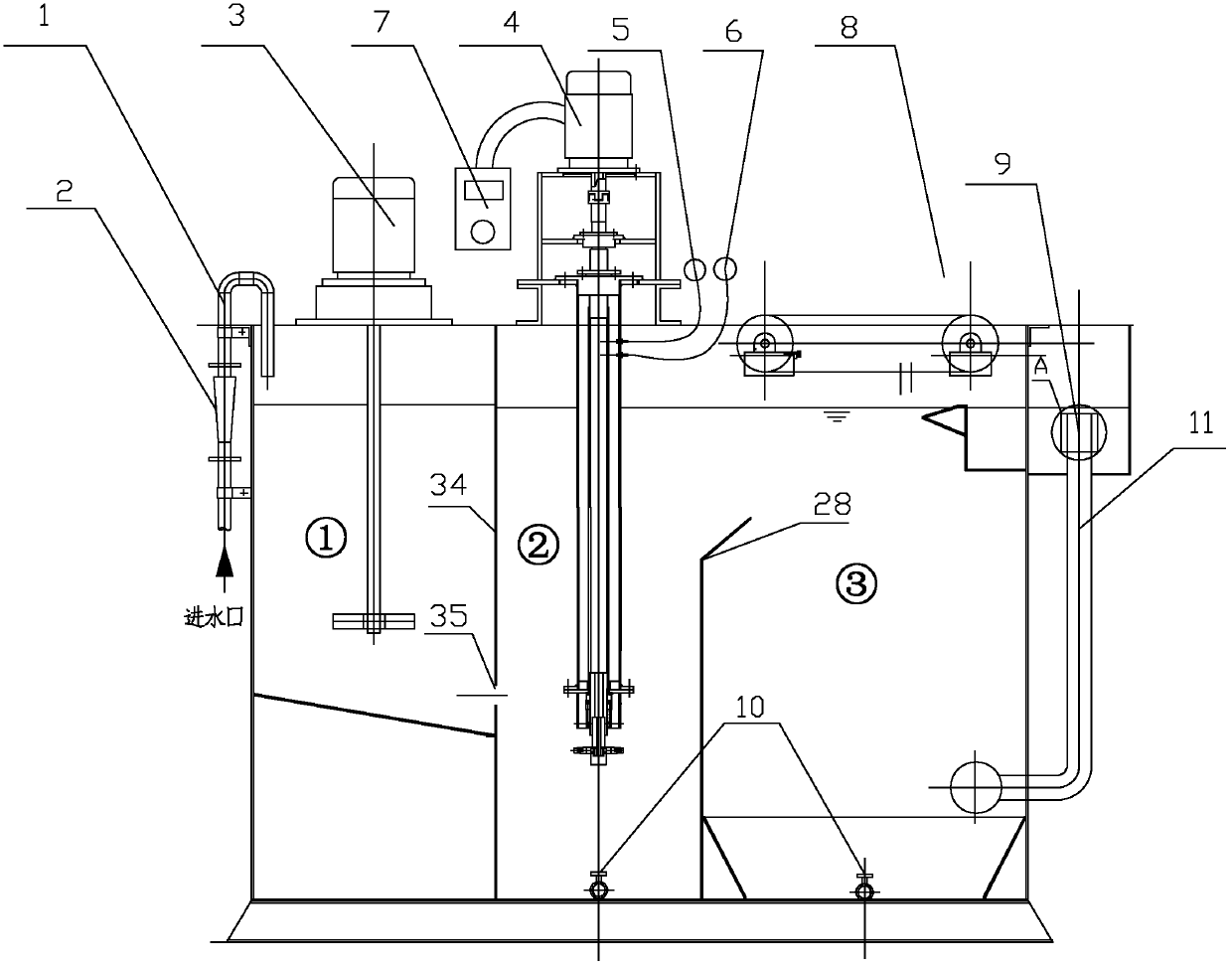
[0026] Such as figure 1 As shown, the reaction tank of the present invention is divided into three parts: dosing mixing area ①, air flotation area ② and separation area ③, wherein the dosing mixing area and the air flotation area are separated by a partition (34), and the air flotation area A deflector (28) is provided between the separation zone and the separation zone;

[0027] The dosing and mixing area ① includes the water inlet pipe (1), the water inlet flowmeter (2) and the dosing mixer (3). The water inlet flowmeter (2) is installed on the water inlet pipe (1) through flange connection, and the dosing mixer (3) is set on the top of the dosing mixing area ① of the reaction tank. There are two flow holes at the bottom of the dosing and mixing area ①, through which the waste water after dosing and coagulation flows into the air flotation area ②.

[0028] The air flotation area ② includes a dissolved air generator (4), an adjustable air flow meter (5), and a vacuum gauge ...


PUM


Abstract

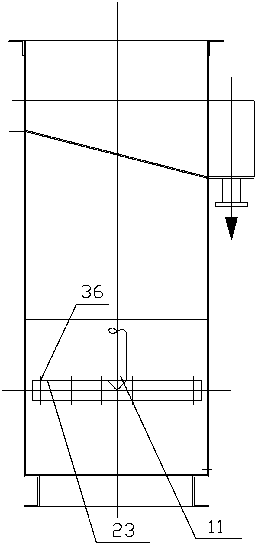
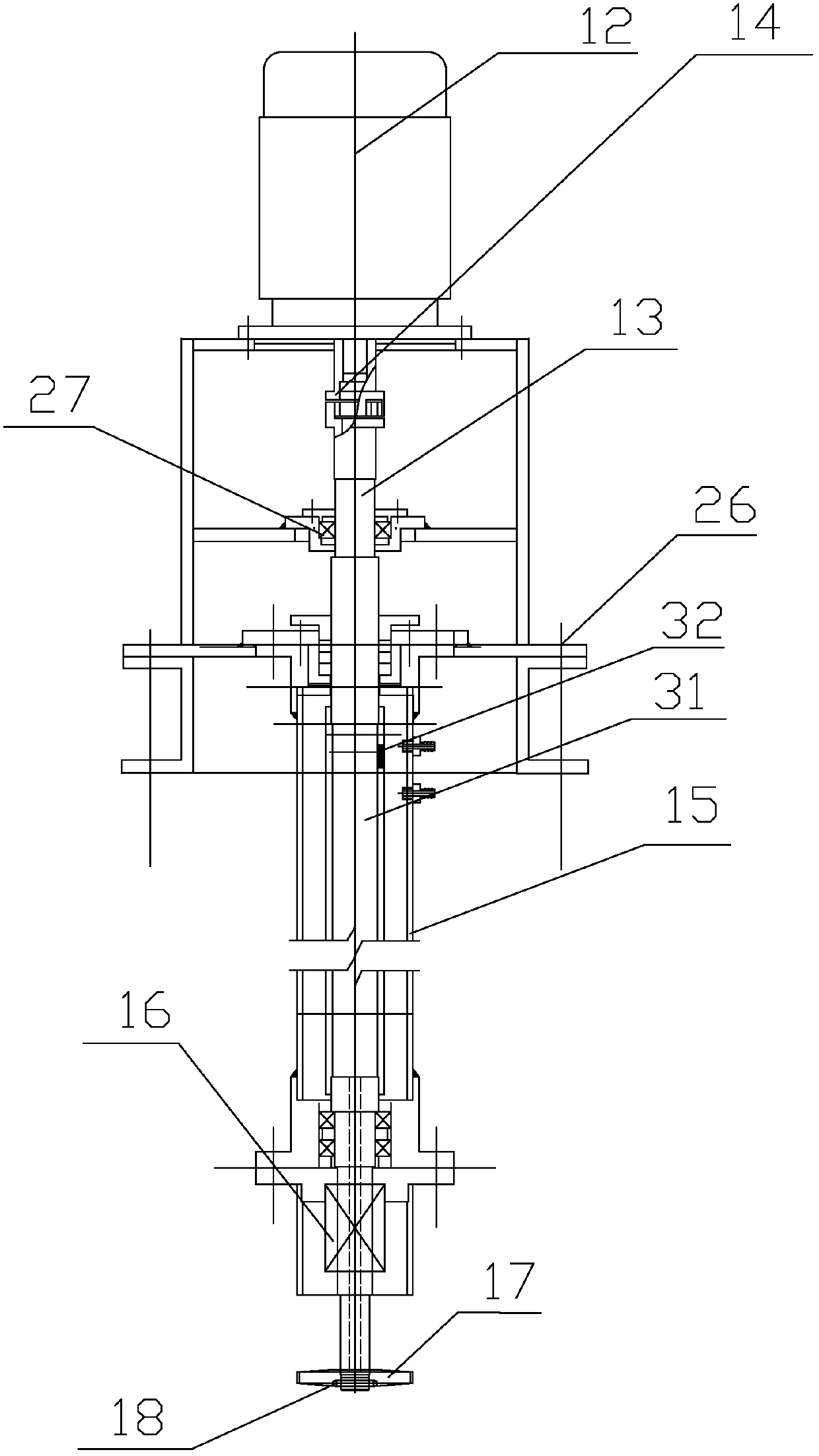
The invention relates to an impeller cutting type vortex air floatation device. For the impeller cutting type vortex air floatation device, a reaction tank is divided into a chemical feeding and mixing area, an air floatation area and a separation area, wherein the chemical feeding and mixing area and the air floatation area are separated by a baffle plate; a flow guide plate is arranged between the air floatation area and the separation area; the chemical feeding and mixing area is provided with a water inlet pipe and a chemical dosing and mixing device; the baffle plate is provided with an overflowing hole; the air floatation area is provided with a dissolved air generator which comprises a motor and a rotating shaft; an adjustable air flow meter and a vacuum meter are arranged on a fixed sleeve which is sleeved on the rotating shaft; the lower end of the rotating shaft stretches out of the sleeve to be connected with an impeller; an air inlet channel which is communicated with an air filling hole in the impeller is arranged inside the rotating shaft; an air vent which is communicated with the air inlet channel is arranged at the upper part of the rotating shaft; a water inlet hole is arranged on an impeller cover; the separation area is provided with a chain residue scraping machine, a liquid level adjusting valve and a water outlet pipe; the water outlet pipe is connected with a horizontal water inlet pipe; and a water outlet hole of the water outlet pipe is provided with the liquid level adjusting valve. The impeller cutting type vortex air floatation device is suitable for the papermaking, leather, oil refining, spinning, printing and dyeing and chemical industries and treatment of municipal sewage and algae-laden water.

Description

technical field [0001] The invention relates to an impeller cutting vortex air flotation device for solid-liquid separation in the field of sewage treatment, which is suitable for treating industrial wastewater such as papermaking wastewater, oily wastewater, petrochemical wastewater, flax wastewater, slaughter wastewater, asphalt wastewater, and tannery wastewater. It mainly removes light suspended solids, grease, colloid, algae and other insoluble organic and inorganic substances in sewage. Background technique [0002] The existing vortex-concave air flotation technology is based on the vortex-concave air flotation system of the American McWong Company. The sewage flows through the turbine of the aerator, and the turbine uses the centrifugal force generated by high-speed rotation to generate negative pressure on the axis of the turbine, sucking in air, and the air flows along the turbine. The four air holes are discharged and broken by the turbine blades, thus forming a l...

Claims


Application Information

Patent Timeline
IPC IPC(8): C02F1/24
Inventor 吕锡武乔春生朱光灿袁俊
Owner SOUTHEAST UNIV
Learn More