
Treatment process of sludge from turbid circulating system of steel enterprise hot rolling factory

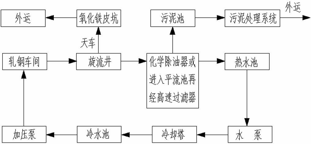
A turbidity ring system and sludge treatment technology, applied in the direction of dewatering/drying/concentrating sludge treatment, etc., can solve the problems of high operating cost, complex treatment process, troublesome operation and management of sludge treatment system, saving civil engineering and The effect of equipment investment, simple process, convenient operation and management

Inactive Publication Date: 2012-07-11
韶关市雅鲁环保实业有限公司
View PDF3 Cites 8 Cited by
  • Summary
  • Abstract
  • Description
  • Claims
  • Application Information

AI Technical Summary

Problems solved by technology

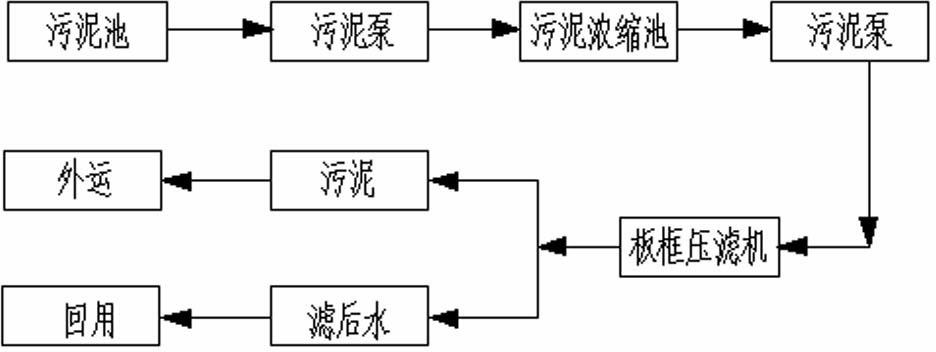
like figure 2 As shown, the existing sludge treatment process of the turbid ring system in the hot rolling mill of the iron and steel enterprise is to enter the sludge deposited by the chemical degreaser or the filter backwash sludge into the sludge in the turbid ring system water treatment process of the hot rolling plant of the iron and steel enterprise. After being evenly stirred by the agitator, it is pumped into the sludge thickening tank with a sludge pump, and then into the plate and frame filter press with a sludge pump with a higher lift. The sludge is dried and transported outside, and the filtered water is returned to For the turbid ring system, the whole treatment process is relatively complicated, and the operation and management are very troublesome. It needs to run the equipment for a long time, and the operating cost of the sludge treatment system is relatively high.

Method used


Image

  • Treatment process of sludge from turbid circulating system of steel enterprise hot rolling factory
  • Treatment process of sludge from turbid circulating system of steel enterprise hot rolling factory
  • Treatment process of sludge from turbid circulating system of steel enterprise hot rolling factory

Examples


Embodiment Construction

[0013] The present invention will be further described below in conjunction with the accompanying drawings and embodiments.

[0014] see image 3 , a sludge treatment process for the turbid ring system in a hot rolling mill of an iron and steel enterprise. The process steps are: the sludge produced in the water treatment process of the turbid ring system in a hot rolling mill of an iron and steel enterprise is first directly discharged from the sludge pool with a sludge pump. Put it into the iron scale pit, and after natural filtration, the water and sludge are separated. The sludge is mixed with the coarse scale iron scale and transported together. The filtered water enters the low-level cyclone well by gravity.

[0015] For example, the mud pump of the sludge treatment system in the turbid ring system of a fully continuous high-grade hot-rolled steel bar production plant with a production capacity of 800,000 tons can use a vertical long-axis pump, Q=50m 3 / h, two sets, one ...


PUM


Abstract

The invention relates to a treatment process of sludge from a turbid circulating system of a steel enterprise hot rolling factory, and the process comprises the following steps: directly pumping sludge generated during water treatment of a turbid circulating system of a steel enterprise hot rolling factory into an oxide scale pit by a sludge pump, performing natural filtration to separate water from the sludge, mixing the sludge with coarse-grained oxide scale for outward transport together, allowing the water obtained after filtration to enter a whirling well at a low position in a gravity flow mode. Water in sludge is removed by the natural filtration of the oxide scale pit; the process is simple; the operation and management are very convenient; no mechanical equipment such as a filter press, a high-lift sludge pump, and the like is required; intermittent operation can be adopted, which saves a lot of water resources; a certain number of project construction land are saved; a lot of civil construction and equipment investment is saved; a lot of operation management cost is saved; a lot of energy consumption is saved; labor intensity of operators is greatly reduced; and secondary pollution caused in sludge treatment is prevented.

Description

technical field [0001] The invention belongs to the technical field of sewage treatment technology, and relates to a sludge treatment process of the turbid ring system in a hot rolling plant of an iron and steel enterprise with simple process, very convenient operation and management and cost saving 。 Background technique [0002] Such as figure 1 As shown, the current water treatment process of the turbid ring system in the hot rolling plant of the iron and steel enterprise is to directly flow the cooling water of the hot rolling plant equipment into the iron sheet ditch of the workshop, and then flow to the swirl well outside the workshop, and remove large pieces of oxidation in the swirl well through precipitation. The iron sheet is then pumped to the chemical degreaser (or sent to the advection sedimentation tank, and then filtered through a high-speed filter) to remove fine particles of iron oxide and oil. The water from the chemical degreaser is pressurized by the pu...

Claims


Application Information

Patent Timeline
Patent Type & Authority Applications(China)
IPC IPC(8): C02F11/12
Inventor 肖波陈艳波杨松青丁磊林晖刘烨阳贻烽谢锦华
Owner 韶关市雅鲁环保实业有限公司
Learn More