Centrifugal type fusion slag quenching and dry type granulating, and waste heat recovery power generation system and method

A technology for melting slag and waste heat recovery, applied in recycling technology, furnace, waste heat treatment, etc., can solve the problems of wasting water resources, heavy system maintenance workload, consumption of new water, etc., to avoid losses and improve waste heat recovery efficiency. Effect

Active Publication Date: 2012-07-11
NANJING KESEN KENEN ENVIRONMENT & ENERGY
View PDF4 Cites 33 Cited by
  • Summary
  • Abstract
  • Description
  • Claims
  • Application Information

AI Technical Summary

Problems solved by technology

The main defects of the water quenching method are: (1) a large amount of fresh water is consumed, wasting water resources; (2) the sensible heat of slag is not recovered, and waste heat resources are seriously wasted; (3) air pollution (SO 2 , H 2 S and other gaseous sulfides); (4) The system maintenance workload is large; (5) During grinding, the slag must be dried, which still consumes energy
At present, the centrifugal granulation method has a good effect on the granulation of molten slag, but it is not ideal in terms of the quenching effect and the thermal efficiency of slag waste heat recovery.
Moreover, under long-term high-temperature conditions, the transmission and lubrication problems of the centrifugal granulation device have not been well resolved
[0006] At present, the waste heat of molten slag is the only high-temperature waste heat resource that has not been effectively utilized in iron and steel enterprises

Method used


Image

  • Centrifugal type fusion slag quenching and dry type granulating, and waste heat recovery power generation system and method
  • Centrifugal type fusion slag quenching and dry type granulating, and waste heat recovery power generation system and method
  • Centrifugal type fusion slag quenching and dry type granulating, and waste heat recovery power generation system and method

Examples


specific Embodiment

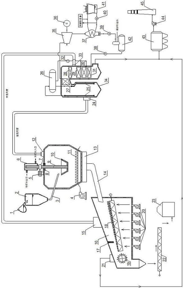
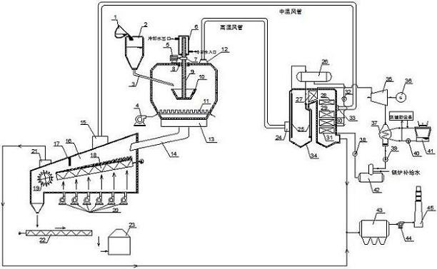
[0028] The specific embodiment that realizes the method of the present invention is as follows:

[0029] 1. The molten slag at 1400-1600°C is sent to the slag storage tank 2 through the slag receiving tank 1 for storage.

[0030] 2. The molten slag in the slag storage tank enters the centrifugal granulation furnace 13 through the slag trough 3, and is broken into small particles below 5mm under the action of the centrifugal granulation device, and the temperature of the slag is lowered by the cold air blown in by the primary blower 4 at the same time. Rapid cooling to about 900°C.

[0031] 3. The water-cooled jacket on the upper part of the heat pipe shaft generates hot water at about 80°C, which enters the pipe network for subsequent central heating or cooling.

[0032] 4. The crushed and quenched slag particles fall onto the water-cooled vibrating grate bed 18 in the cooler 16, and exchange heat with the cold air blown in by the secondary blower 20 of the cooler, and then u...


PUM


Abstract

The invention provides a centrifugal type fusion slag quenching and dry type granulating system and method and a waste heat recovery power generation system and method, belongs to steel metallurgy slag treatment and waste heat recovery technology fields. The system of the invention comprises a slag receiving device, a slag centrifugal type quenching and granulating device, a slag slow cooling device, a waste heat recovery power generation device and an exhaust gas purifying and treating device. The system quenches and granulates the fused slag by the special centrifugal type quenching and granulating device, and rapidly cools the slag into a viterous body state. Then the slag is further slowly cooled by a water-cooled type vibration grate, and the waste heat recovered in the quenching andslow cooling processes generates steam by a binary channel type exhaust-heat boiler, which drives a turbo generator set for power generation. The system and the method effectively resolves the problem of long-time, safety and stabilization operation of a centrifugal type granulation device, and implements fused slag quenching and dry type granulation, and on the basis of non-influence on followedutilization value, the system and the method can high-efficiency and fully recover the high temperature waste heat resource of the slag.

Description

technical field [0001] The invention belongs to the technical field of iron and steel metallurgical slag treatment and residual energy recovery, and in particular relates to a centrifugal melting slag quenching dry granulation and waste heat recovery power generation system and a method thereof. Background technique [0002] According to the data, the energy consumption of China's iron and steel industry accounts for 10-15% of the country's total energy consumption. A large amount of slag will be produced in the production of iron and steel, and 0.3-0.6 tons of blast furnace slag will be produced for every ton of pig iron produced. 0.13 tons of steel slag should be produced as a by-product of steel products. The above-mentioned molten slag has an initial temperature as high as 1400-1600°C and is rich in a large amount of sensible heat resources. If it is not utilized or directly quenched with water, it will seriously waste energy and pollute the ecological environment. [0...

Claims


Application Information

Patent Timeline
Patent Type & Authority Applications(China)
IPC IPC(8): C21B3/06C21B3/08F27D17/00
CPCC21B2400/026C21B2400/034C21B2400/052C21B2400/054C21B2400/08Y02P10/25Y02W30/50
Inventor 何张陈刘亚雷宋纪元侯宾才杨宏宜王效平刘学炉
Owner NANJING KESEN KENEN ENVIRONMENT & ENERGY
Why Eureka
Try Eureka