Spectrum analyzer and spectrum analyzing method

A spectrum analyzer and spectroscopic technology, applied in the field of spectrum analyzer and spectrum analysis, can solve the problem of poor spectral resolution in narrow band, and achieve the effect of low cost, wide coverage of wavelength range, and improved optical resolution

Active Publication Date: 2012-07-11
FOCUSED PHOTONICS
View PDF8 Cites 14 Cited by
  • Summary
  • Abstract
  • Description
  • Claims
  • Application Information

AI Technical Summary

Problems solved by technology

[0014] In order to solve the above-mentioned deficiencies in the prior art, the present invention provides a spectrum analyzer and a spectrum analysis method with low cost and high reliability, which can improve the problem of poor narrow-band spectral resolution of the traditional echelle two-dimensional spectroscopic system

Method used


Image

  • Spectrum analyzer and spectrum analyzing method
  • Spectrum analyzer and spectrum analyzing method
  • Spectrum analyzer and spectrum analyzing method

Examples


Embodiment 1

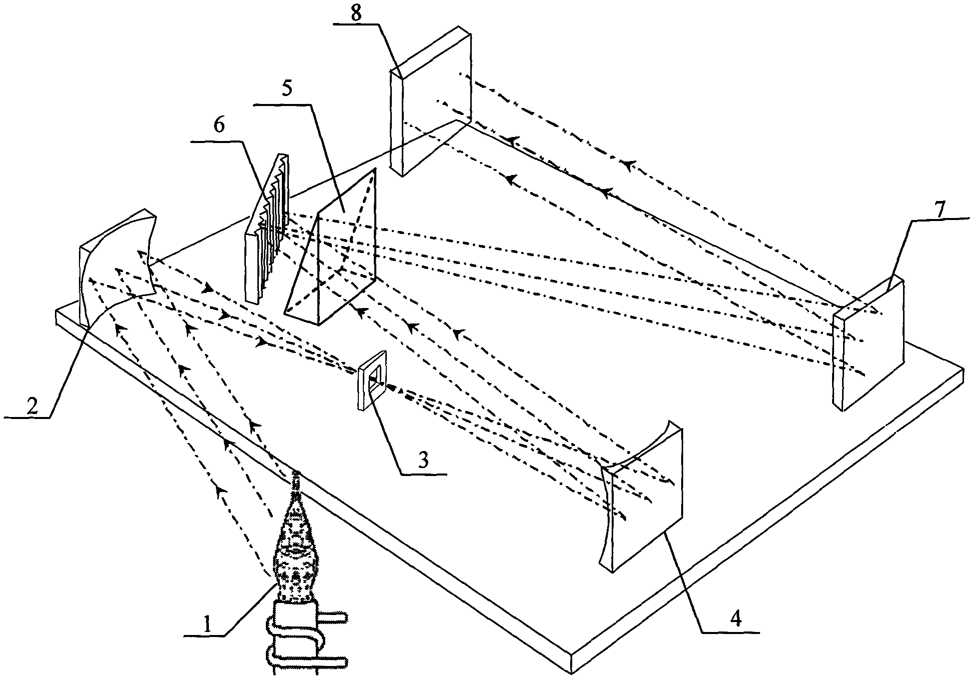
[0047] see figure 2 , image 3 , a spectrum analyzer, comprising a light source, a light collection unit, a spectroscopic unit, an imaging unit, a detection unit and a processing unit;

[0048] In the present invention, the light source 11 is one of inductively coupled plasma (ICP), laser, element lamp, xenon lamp, flame, etc., and this embodiment is an ICP light source. Inductively coupled high-frequency plasma light source is the most commonly used light source for atomic emission spectroscopy. Usually, it is composed of four parts: high-frequency generator, induction coil, plasma torch and gas supply system;

[0049] The light collection unit includes a focusing mirror 12 , an entrance slit 13 and a focusing mirror 14 , and the light collection unit couples the measurement light emitted by the light source 11 to the first spectroscopic module. The light source and the light collection unit are prior art in this field, and will not be repeated here.

[0050] The spectros...

Embodiment 2

[0075] A kind of spectrum analyzer, different from the spectrum analyzer described in embodiment 1 is:

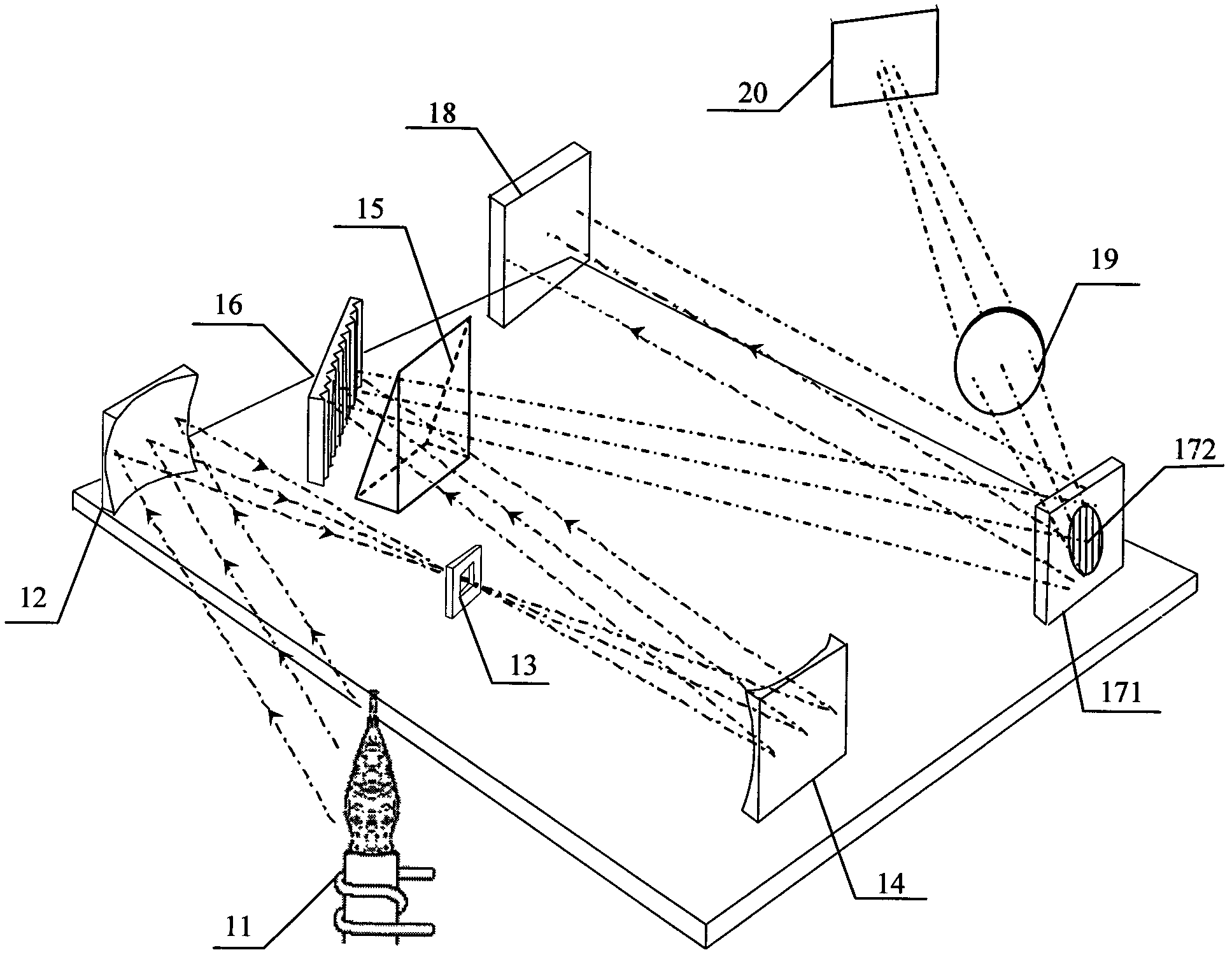
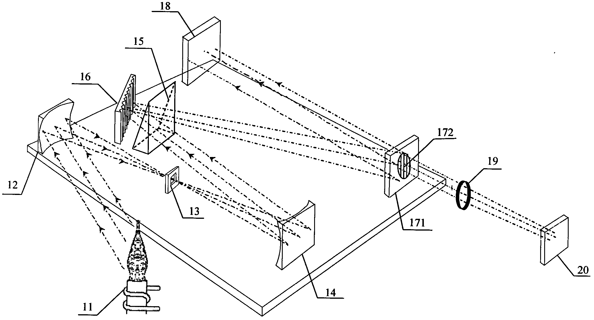
[0076] The first imaging module 27 and the second light splitting module 272 are mutually independent devices, and the second light splitting module 272 is arranged between the first light splitting module and the first imaging module 27, as Figure 6 shown, or arranged between the first imaging module 27 and the first detector 18, such as Figure 7 shown. The second light splitting module is a reflection or transmission concave grating. In this embodiment, the second light splitting module 272 is a transmission concave grating.

[0077] The measurement light is split by the first spectroscopic module and then split by the second spectroscopic module 272. The second spectroscopic module splits the 1st-level light from the 0-level light, and the 0-level light does not introduce additional spectroscopic ability. Therefore, on the first detector 18 The obtained spectrogram m...

Embodiment 3

[0082] see Figure 8 , a kind of spectrum analyzer, is different from the spectrum analyzer described in embodiment 2:

[0083] The imaging unit only includes the second imaging module 19, and the detection unit only includes the second detector 20;

[0084] In this embodiment, the narrow wavelength band is a long wavelength band of 500 nm to 650 nm.

[0085] This embodiment also provides a spectral analysis method, which is different from the spectral analysis method in Example 2:

[0086] 1, in step A, adopt the spectrum analyzer of the present embodiment;

[0087] 2. After the measurement light is split by the first spectroscopic module, it is split by the second spectroscopic module 272. The second spectroscopic module 272 splits the primary light and processes the primary light received by the second detector 20 to obtain a higher resolution Spectrograms corresponding to narrow bands such as long bands of capability.


PUM


Abstract

The invention relates to a spectrum analyzer, which comprises a light source, a light collecting unit, a light splitting unit, an imaging unit, a detecting unit and a processing unit. The light source emits measuring light. The light collecting unit couples the measuring light to the light splitting unit which comprises a first light splitting module and a second light splitting module. The measuring light is split by the first light splitting module in an X direction, split by the second light splitting module in the same direction, imaged by the imaging unit and then received by the detecting unit. Signals received by the detecting unit are processed by the processing unit so as to obtain a spectrogram corresponding to a narrow wave band. The invention further provides a spectrum analyzing method. The spectrum analyzer and the spectrum analyzing method have the advantage of high spectral resolution of the narrow wave band.

Description

technical field [0001] The invention relates to a spectrum analyzer and a spectrum analysis method, in particular to a spectrum analyzer and a spectrum analysis method which can effectively improve the resolution of a narrow-band spectrum. Background technique [0002] In the field of spectral detection, it is generally required that the spectral acquisition time should be as short as possible, and the spectral range of one acquisition should be as wide as possible; the entire detection system should be firm and compact, easy to carry and use outdoors; Minimize the workload of calibration and various drift compensations. [0003] At present, common spectrometer structures include Czerny-Turner structure, Paschen-Runge structure, flat-field concave grating spectroscopic system, echelle two-dimensional spectroscopic system, etc. [0004] Due to its advantages of small size and high resolution, the echelle grating two-dimensional spectroscopic system is widely used in occasion...

Claims


Application Information

Patent Timeline
Patent Type & Authority Applications(China)
IPC IPC(8): G01J3/28
Inventor 俞晓峰顾海涛吕全超李萍俞大海王健
Owner FOCUSED PHOTONICS
Why Eureka
Try Eureka