
Layout optimizing method for phased-array antennas on large-scale ship plane

A layout method and large-scale technology, applied in special data processing applications, instruments, electrical digital data processing, etc., can solve problems such as electromagnetic interference

Active Publication Date: 2012-07-11
CHINA SHIP DEV & DESIGN CENT
View PDF3 Cites 20 Cited by
  • Summary
  • Abstract
  • Description
  • Claims
  • Application Information

AI Technical Summary

Problems solved by technology

Due to the propagation characteristics of electromagnetic waves, there will be electromagnetic coupling between different antennas, and the result of coupling may cause electromagnetic interference

Method used


Image

  • Layout optimizing method for phased-array antennas on large-scale ship plane
  • Layout optimizing method for phased-array antennas on large-scale ship plane
  • Layout optimizing method for phased-array antennas on large-scale ship plane

Examples


Embodiment Construction

[0076] The method for optimizing the layout of large-scale planar phased array antennas for ships is characterized in that it includes the following steps:

[0077] 1) For two array antennas arranged on the plane of the ship, one of them is assumed to be the transmitting array antenna, and the other is the interfered (or receiving) array antenna, and the port current of the transmitting array antenna is obtained.

[0078] The entire system consisting of a transmitting array antenna with N array elements and an interfered array antenna with N′ array elements is regarded as a linear network with N+N′ ports, and the excitation voltage and response current satisfy:

[0079] V=ZI(1),

[0080] V, I, and Z are respectively the port excitation voltage, response current, and port mutual impedance matrix of the two array antennas;

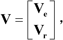
[0081] V, I, Z can be expressed as

[0082] V = V e ...


PUM


Abstract

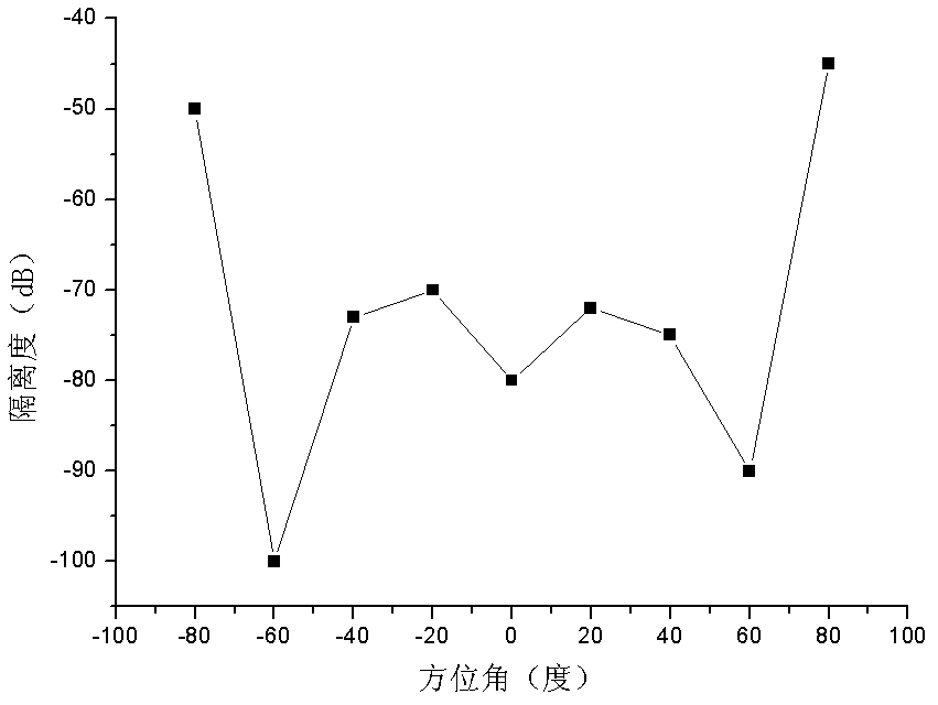
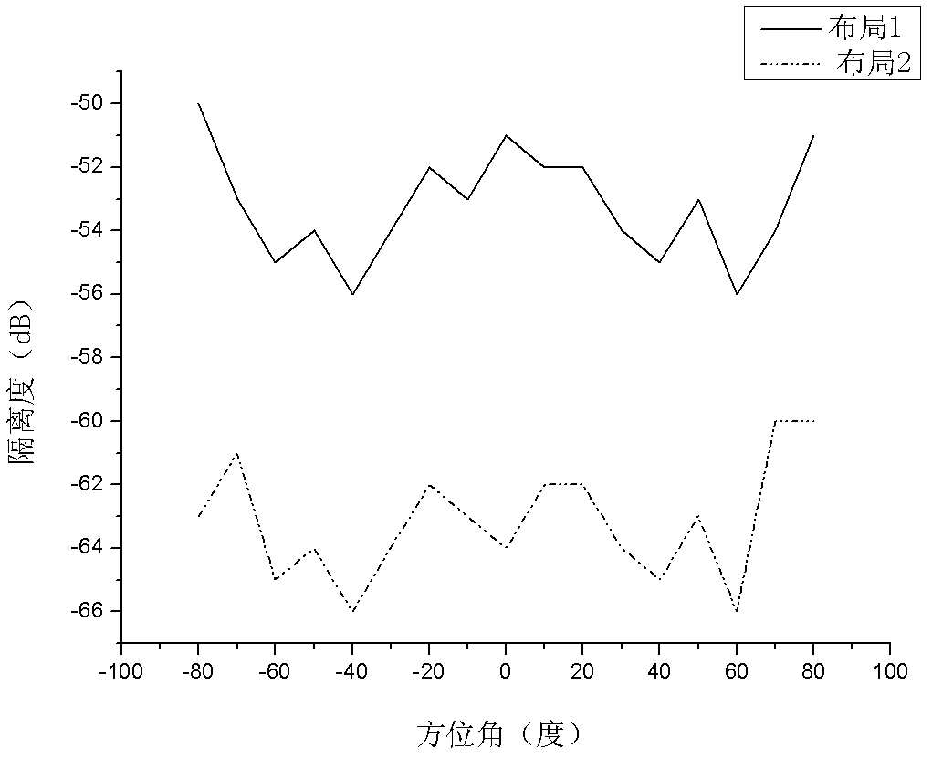
The invention provides a layout optimizing method for phased-array antennas on a large-scale ship plane, which includes the following steps: 1) setting two array antennas on the ship plane as an emitting array antenna and an interfered array antenna, and solving a port current of the emitting array antenna; 2) solving the port current of the interfered array antenna according to the port current of the emitting array antenna and mutual-impedance matrix between the array antennas; 3) measuring cross coupling between the array antennas by isolation, defining as shown, setting the Pr as emittingpower of the emitting array antenna and the Ps as receiving power of the interfered array antenna; 4) disposing the emitting array antenna and the interfered array antenna at different positions, changing beam direction (azimuthal angle and pitch angle) of the emitting array antenna so as to obtain a curve of isolation changing along with the beam direction, comparing the values of the isolation obtained at different positions, and selecting the positions with low isolation in all directions as the optimum layout of the array antennas.

Description

technical field [0001] The patent of the invention belongs to the technical field of antenna and electromagnetic compatibility, and specifically relates to a method for optimizing the layout of a large-scale planar phased array antenna of a ship. Background technique [0002] Phased array radar is more and more widely used in different industrial fields (meteorology, navigation, etc.). Phased array radar can be installed on system platforms such as ships. Phased array radar usually adopts a planar array antenna including thousands of array elements, each of which is also an independent antenna. In order to cover the entire space in 360-degree azimuth, four planar array antennas are usually required, and each antenna covers a 90-degree azimuth space. 4 antennas are distributed on different surfaces of the superstructure of the ship's polyhedral structure. When multiple radars are installed on a ship, more antennas are arranged on the superstructure. Due to the propagation...

Claims


Application Information

Patent Timeline
Patent Type & Authority Applications(China)
IPC IPC(8): G06F17/50
Inventor 王春吴楠谢大刚
Owner CHINA SHIP DEV & DESIGN CENT
Learn More