Triggering and conducting method used for switching of capacitor of thyristor AC non-contact switch

A non-contact switch, switching capacitor technology, used in reactive power compensation, reactive power adjustment/elimination/compensation, etc., can solve the problems of insufficient control accuracy, affecting safety and reliability, and complex current waveform detection and control. Simple control method, great economic and social benefits, no gap in current waveform

Active Publication Date: 2012-07-11
郑学超
View PDF4 Cites 9 Cited by
  • Summary
  • Abstract
  • Description
  • Claims
  • Application Information

AI Technical Summary

Problems solved by technology

[0012] In order to overcome the problems in the prior art, such as insufficient control precision in the trigger pulse control of the SVC-TSC reactive power dynamic compensation device, gaps in the current waveform and complicated detection and control, which affect safety and reliability, the patent of the present invention proposes a Thyristor non-contact

Method used


Image

  • Triggering and conducting method used for switching of capacitor of thyristor AC non-contact switch
  • Triggering and conducting method used for switching of capacitor of thyristor AC non-contact switch
  • Triggering and conducting method used for switching of capacitor of thyristor AC non-contact switch

Examples


Embodiment 1

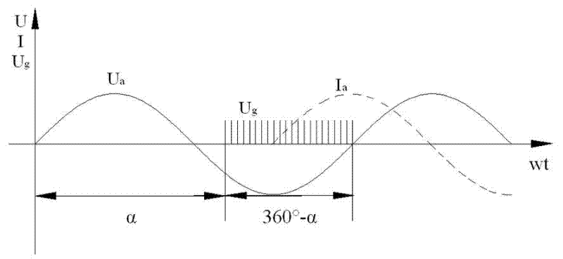
[0035] Reactive power compensation controller and trigger pulse board, there are many types of products on the market can be selected, this embodiment uses a three-phase bridge full-control rectification trigger board Type 6.0 standard trigger board, a thyristor AC non-contact trigger board in this embodiment The method of triggering conduction when the switch is switched on and off is to use the multi-turn potentiometer on the trigger board to detect with an oscilloscope and adjust the control angle α to 210°. Specifically, first adjust the control angle α to 30° (210° -180°=30°), and then invert the synchronous power signal to get the control angle α to be 210°, which is fixed, then change the small capacitor of the circuit on the trigger board to a larger size, and increase the pulse width to 150° (360° °-210°=150°), also fixed. Therefore, the control system becomes very simple and reliable, and there is no current impact when the capacitor is switched on.

[0036] In this...

Embodiment 2

[0038] The basic steps are the same as in Example 1, the difference is that the control angle α is adjusted to 200° through the oscilloscope detection and remains unchanged, specifically, the control angle α is first adjusted to 20° (200°-180°=20°) , and then invert the synchronous power supply signal to obtain a control angle α of 200°; the pulse width is adjusted to 160°, which is also fixed. Thyristor AC non-contact switch triggers conduction when switching capacitors, high control precision, no current impact when capacitors are switched in, complete waveform, smooth zero crossing, no gaps and no harmonics.

Embodiment 3

[0040] The basic steps are the same as in Example 1, the difference is that the control angle α is adjusted to 220° through the oscilloscope detection and remains unchanged, specifically, the control angle α is first adjusted to 40° (220°-180°=40°) , and then invert the synchronous power supply signal to obtain a control angle α of 220°; the pulse width is adjusted to 140°, which is also fixed. Thyristor AC non-contact switch triggers conduction when switching capacitors, high control precision, no current impact when capacitors are switched in, complete waveform, smooth zero crossing, no gaps and no harmonics.


PUM


Abstract

The invention discloses a triggering and conducting method used for the switching of a capacitor of a thyristor AC non-contact switch, belonging to the field of triggering and conducting method of thyristors. The method comprises the following steps of: (1) regulating a multi-turn potentiometer on a triggering pulse plate, adjusting the control angle alpha to 180-270 degrees, and keeping the value of the control angle alpha unchanged; (2) regulating the capacitance of a return circuit on the triggering pulse plate, so that the triggering pulse width is 360-alpha degrees, and keeping the triggering pulse width unchanged until the anode potential is higher than the cathode potential and the capacitor current arises smoothly from zero. By using the triggering and conducting method, inrush current and operation overvoltage are avoided during switching of the capacitor, a compensating device itself does not generate harmonic wave, the control system is simple and reliable, the control precision is high, the current waveform does not have notches, and greater economic and social benefits are achieved in reducing the grid loss and voltage fluctuation, improving the grid quality, enhancing the grid safety, etc.

Description

technical field [0001] The present invention relates to a method for controlling the trigger conduction of thyristor, more specifically, it relates to a reactive power dynamic compensation device (abbreviation: SVC-TSC) of thyristor AC non-contact switch switching capacitor, and its trigger conduction method , that is, a safe and simple method to determine the thyristor trigger pulse control angle α. Background technique [0002] The reactive power dynamic compensation device is an indispensable equipment in the power grid. It can not only reduce the loss of the power grid and improve the transmission capacity of the line, but more importantly, it can reduce the voltage fluctuation and improve the quality, safety and reliability of the power grid. The old dynamic compensation of reactive power is to install the camera (rotating machine) in the power plant or the regional center substation. In addition, fixed reactive power compensation with vacuum circuit breaker switching ...

Claims


Application Information

Patent Timeline
IPC IPC(8): H02J3/18
CPCY02E40/30
Inventor 郑学超
Owner 郑学超
Why Eureka
Try Eureka