
Constant voltage constant current control circuit and control method thereof

A control circuit, constant voltage and constant current technology, applied in the direction of control/regulation system, electrical components, and adjustment of electrical variables, etc., can solve the problems of inaccurate feedback control, many circuit components, complex implementation, etc., to achieve accurate control, circuit The effect of simple structure and fewer circuit components

Active Publication Date: 2012-07-11
SILERGY SEMICON TECH (HANGZHOU) CO LTD
View PDF3 Cites 41 Cited by
  • Summary
  • Abstract
  • Description
  • Claims
  • Application Information

AI Technical Summary

Problems solved by technology

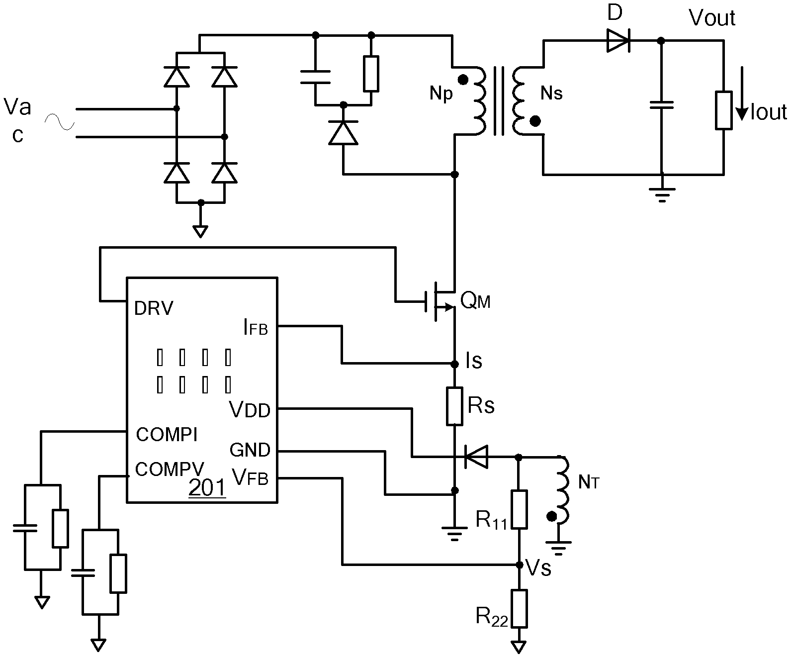
[0005] the above figure 2 Although the constant voltage and constant current control device shown in is reduced in size and cost, but in the working process of the flyback converter, when the secondary winding N S discharged to zero current, the auxiliary winding N T The coupled voltage on will drop sharply, therefore, by the auxiliary winding N T feedback to obtain the output voltage feedback signal V FB It cannot accurately follow the change of the actual converter output voltage, and may even have a large deviation, resulting in inaccurate feedback control
In addition, the implementation of the existing integrated circuit control unit is relatively complicated. For example, its constant voltage control loop and constant current control loop still need external compensation circuits for control and adjustment, and there are many circuit components.

Method used


Image

  • Constant voltage constant current control circuit and control method thereof
  • Constant voltage constant current control circuit and control method thereof
  • Constant voltage constant current control circuit and control method thereof

Examples


Embodiment Construction

[0055] Several preferred embodiments of the present invention will be described in detail below with reference to the accompanying drawings, but the present invention is not limited to these embodiments. The present invention covers any alternatives, modifications, equivalent methods and schemes made on the spirit and scope of the present invention. In order to provide the public with a thorough understanding of the present invention, specific details are set forth in the following preferred embodiments of the present invention, but those skilled in the art can fully understand the present invention without the description of these details.

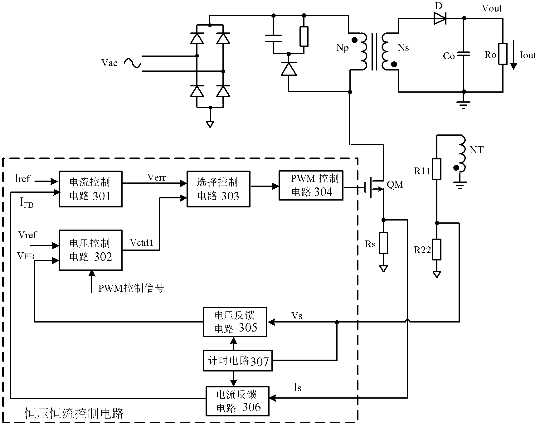
[0056] refer to image 3 , which is a circuit diagram of the first embodiment of a constant voltage and constant current control circuit according to the present invention, image 3 The shown constant voltage and constant current control circuit is applied in a flyback converter, and the flyback converter includes a power stage circuit, ...


PUM


Abstract

The invention relates to a constant voltage constant current control circuit and a constant voltage constant current control method thereof, and is applied to a flyback converter. The constant voltage constant current control circuit generates a constant voltage / constant current control signal according to an output voltage feedback signal and an output current feedback signal to control the duty ratio of a switching signal of a main switching tube in the flyback converter and further ensure that the output voltage or output current of the flyback converter is kept constant. A circuit coupling control scheme is adopted, and then constant voltage or constant current control can be realized only by one capacitor, so that the constant voltage constant current control circuit has a simple structure; and moreover, the output voltage feedback signal which precisely represents the output voltage information of a secondary side and the output current feedback signal which precisely represents the output current information of the secondary side can be obtained by a voltage feedback circuit and a current feedback circuit, so that the constant voltage constant current control circuit is high in accuracy.

Description

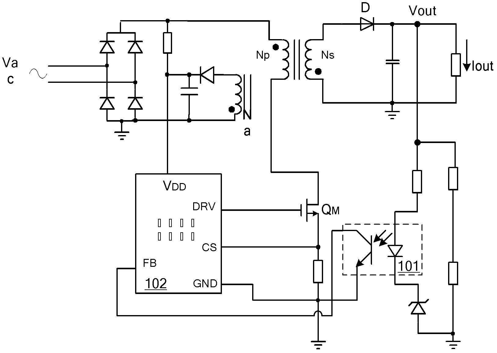
technical field [0001] The present invention relates to the field of switching power supplies, more specifically, to a constant voltage and constant current control circuit and a control method thereof. Background technique [0002] With the rapid development of the power supply industry, the application of switching power supplies using constant voltage and constant current control is becoming more and more extensive, and its design requirements for control circuits are also getting higher and higher. the greatest goal pursued. [0003] figure 1 Shown is a conventional constant voltage and constant current control device of a flyback converter controlled by the secondary side, which adjusts the output voltage and output current through a sampling resistor, an optocoupler 101 and a secondary side feedback control circuit 102 control, the sampling resistor (including voltage sampling resistor and current sampling resistor) is used to sample the secondary output voltage and ...

Claims


Application Information

Patent Timeline
Patent Type & Authority Applications(China)
IPC IPC(8): H02M3/335
CPCH02M3/33507H02M3/335
Inventor 徐孝如
Owner SILERGY SEMICON TECH (HANGZHOU) CO LTD
Learn More