
Feedforward automatic gain control circuit working in extremely low voltage current mode

A technology of automatic gain control and power supply voltage, applied in the direction of gain control, amplification control, electrical components, etc., can solve the problems of large power consumption, complex compensation circuit, low signal processing accuracy, etc., achieve low power consumption and solve continuity and the effect of precision

Active Publication Date: 2012-07-11
INST OF ELECTRONICS CHINESE ACAD OF SCI
View PDF3 Cites 12 Cited by
  • Summary
  • Abstract
  • Description
  • Claims
  • Application Information

AI Technical Summary

Problems solved by technology

Usually, the magnification of the op amp has achieved ideal precision under the control of analog feedback, but it is extremely difficult to achieve high precision in integrated circuits, which usually requires complex compensation circuits or very large power consumption
The disadvantage of the current mode feedback method is that the op amp itself does not have a negative feedback structure, so the accuracy of the system for signal processing is low
However, digital hearing aids require the readout circuit to have very good readout accuracy, which poses a challenge to the design of the readout circuit

Method used


Image

  • Feedforward automatic gain control circuit working in extremely low voltage current mode
  • Feedforward automatic gain control circuit working in extremely low voltage current mode
  • Feedforward automatic gain control circuit working in extremely low voltage current mode

Examples


Embodiment Construction

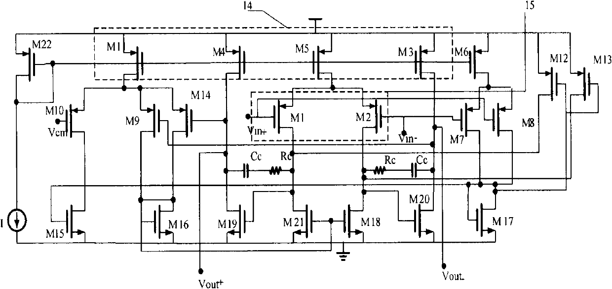
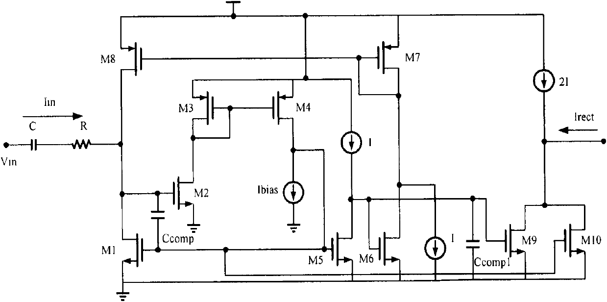
[0037] The present invention provides a current mode feed-forward automatic gain control circuit that works on extremely low power supply voltage, and effectively solves the existing problems in the prior art by adopting a circuit module that works on low power supply voltage, current mode feedforward and digital circuit control. non-linear problem.

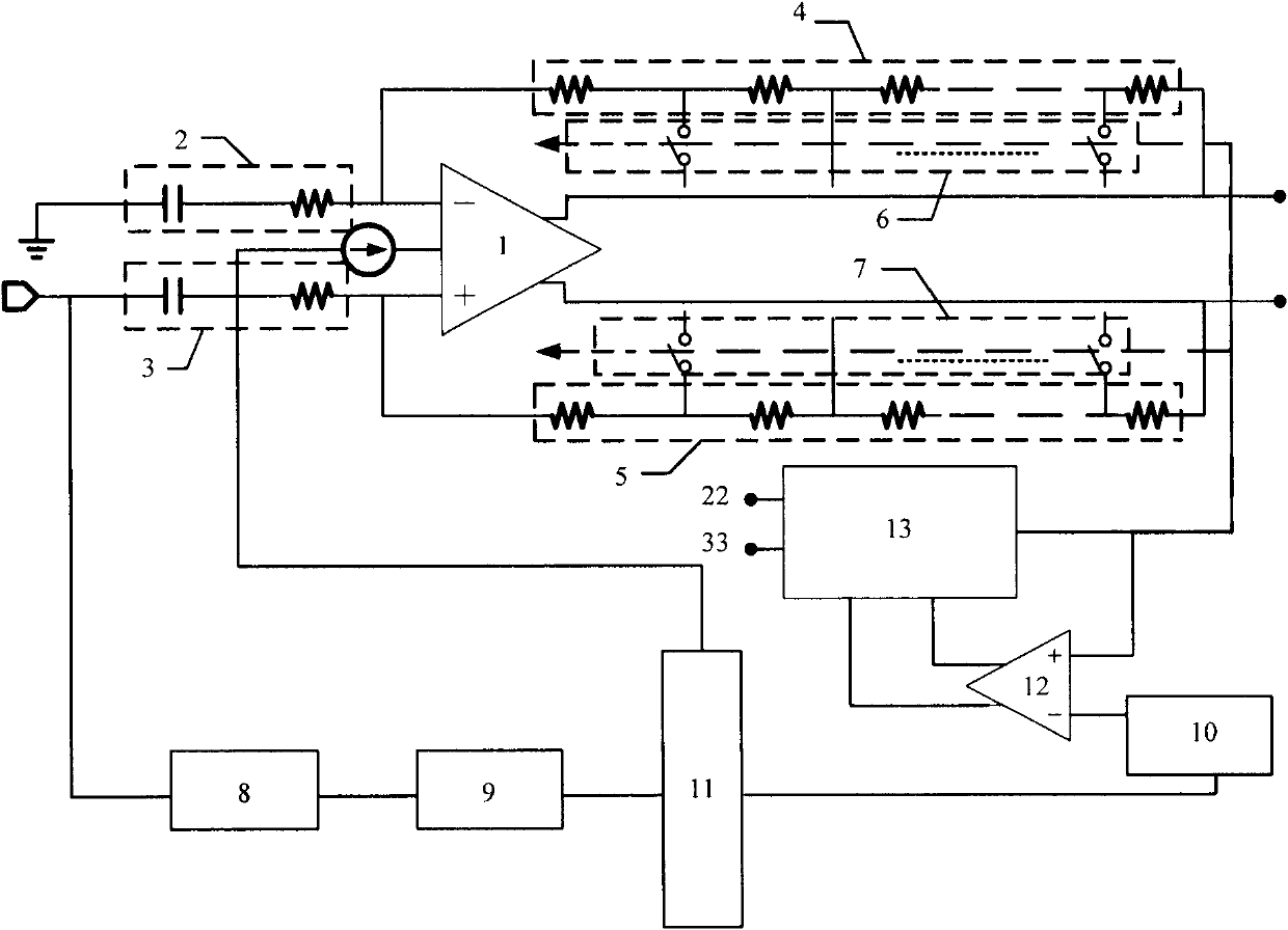
[0038] In the present invention, capacitive resistance devices 2 and 3 perform high-pass on the microphone DC signal, filter the microphone DC signal, and read out the weak signal of the microphone by the fully differential operational amplifier circuit 1; at the same time, the envelope detection circuit composed of the rectifier 8 and the filter 9 detects The energy of the weak microphone signal, the digital controller 11 processes the energy to obtain a digital control signal, the digital reference table 10 finds the corresponding gain control code according to the digital control signal, applies it to the digital comparator 12,...


PUM


Abstract

The invention provides a feedforward automatic gain control circuit working in an extremely low voltage current mode, and relates to the technology of sensors. The feedforward automatic gain control circuit comprises a fully differential operational amplification unit, a capacitive-resistance device, a resistor array, a control switch, rectifier, a filter, a controller, a digital reference table, a digital comparator and an add-subtract counter, wherein the fully differential operational amplification unit is used for correspondingly amplifying voltage signals of an output end of a microphone according to variation of the resistance array; the rectifier is used for converting the voltage signals into current signals and rectifying current; the filter is used for filtering the current output by the rectifier and carrying out envelop detection on input signals; the digital controller is used for comparing current output by the filter with the reference current to obtain digital control signals in the digital reference table; the digital comparator is used for comparing output of the add-subtract counter with the digital control signals, when the sound volume is in different levels, the amplifying multiple of the fully differential operational amplification unit is adjusted, so that the hearing of the auditorily handicapped is protected; when the sound volume is in a normal state, the amplifying multiple of the fully differential operational amplification unit is restored to the original value, so that the automatic gain control on the different sound volumes is realized.

Description

technical field [0001] The invention relates to the technical field of microphone sensors, relates to a high-precision readout circuit chip suitable for a microacoustic electric system (MEMS) microphone sensor, and is an automatic gain control circuit for a digital hearing aid microphone readout circuit chip. Background technique [0002] With the continuous advancement of micro-acoustic electric system (MEMS) technology, micro-acoustic electric hearing aid microphone sensors have emerged at the historic moment. It has the advantages of small size, low power consumption, small distortion and strong anti-noise ability. The corresponding readout circuit become a research hotspot in the industry. [0003] This kind of sensor can usually be equivalent to a relatively ideal voltage source: a small resistance on the ideal voltage source string. However, the signal output by the microelectromechanical sensor of the microphone is very weak, generally only in the order of μV ~ mV, w...

Claims


Application Information

Patent Timeline
IPC IPC(8): H03G3/20
Inventor 杨海钢李凡阳
Owner INST OF ELECTRONICS CHINESE ACAD OF SCI
Learn More