Drill for composite material as well as machining method using same and machining apparatus using same

A composite material and mechanical processing technology, which is applied in the direction of reaming devices, metal processing equipment, and cutting tools for lathes, etc., can solve the problems of flashing in the perforated part and increased cutting resistance, so that it is not easy to peel off layers, Effects of reduced cutting resistance and high-precision piercing

Inactive Publication Date: 2012-07-11
FUKUI PREFECTURE
View PDF9 Cites 6 Cited by
  • Summary
  • Abstract
  • Description
  • Claims
  • Application Information

AI Technical Summary

Problems solved by technology

[0003] However, when piercing is performed at one time by this method, the cutting resistance at the time of piercing becomes large, and burrs tend to be generated in the piercing portion.

Method used


Image

  • Drill for composite material as well as machining method using same and machining apparatus using same
  • Drill for composite material as well as machining method using same and machining apparatus using same
  • Drill for composite material as well as machining method using same and machining apparatus using same

Examples


no. 1 approach

[0041] Regarding the embodiment of the present invention, when the present invention is applied to a two-blade drill having two torsion grooves, as the first embodiment of the present invention, the linear portion is formed in the shape of a reamer, and as the second embodiment The method is to form the straight portion into a land drill shape, which will be described with reference to the drawings.

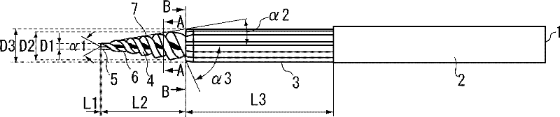
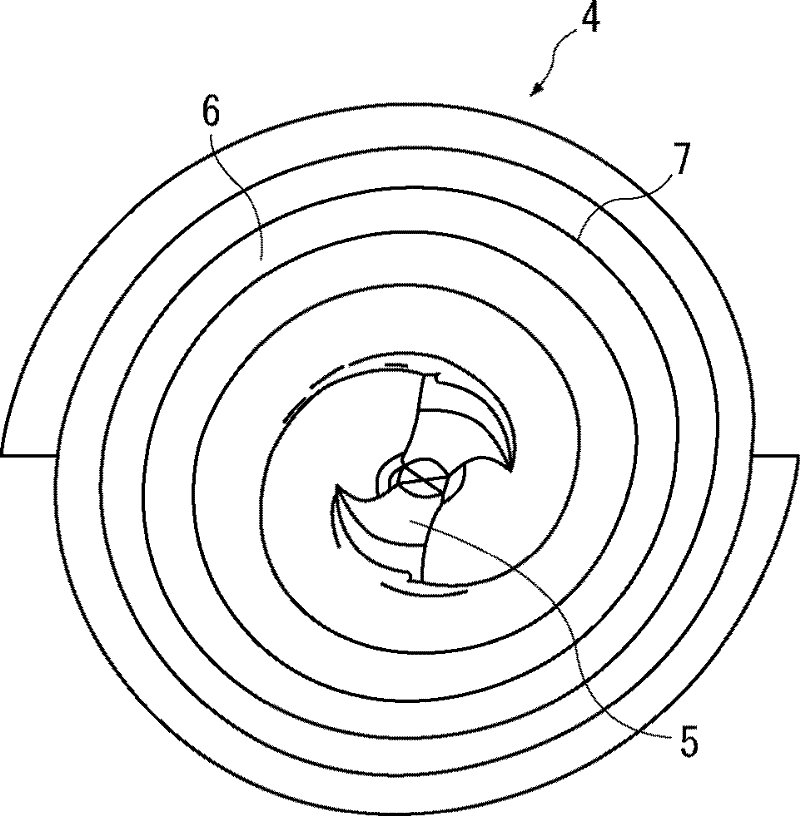
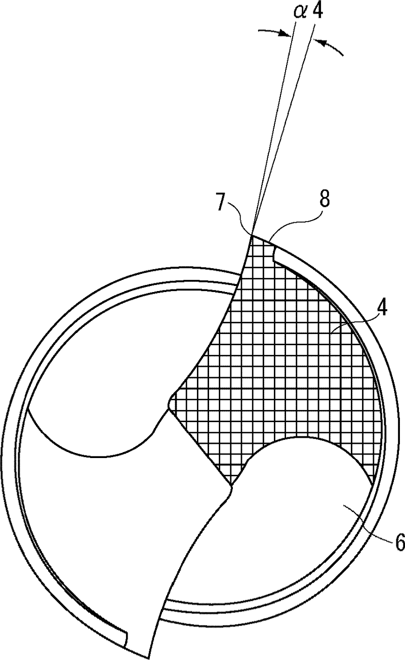
[0042] refer to Figure 1 ~ Figure 4 The first embodiment according to the present invention will be described. figure 1 It is a side view of the drill 1 of the first embodiment. figure 2 It is viewed from the front side toward the rear end side figure 1 The front view obtained from the tapered part. image 3 yes figure 1 A cross-sectional view of the A-A line. Figure 4 yes figure 1 The cross-sectional view of the B-B line.

[0043] The drill 1 according to the present embodiment is a two-blade drill formed by connecting a straight portion 3 forming a reamer to the front...

Embodiment 1

[0078] Such as Figure 5 As shown, a cutting test was performed on a drill including a tip portion having a tip cutting edge, a tapered portion formed with a peripheral cutting edge, and a straight portion, and the thrust resistance (force applied in the drill axial direction) was measured.

[0079] In the cutting test, the cutting edge with no margin on the peripheral cutting edge was used. Figure 5 The four types of drills shown and the three types of drills as comparative examples make a total of seven types of drills.

[0080] as Figure 5 For the drills shown, the following three drills A to C are used. That is, the base material of the drill is cemented carbide and diamond coating. The following are general specifications: the tip angle of the tip of the drill is β1 = 135°, and the overall length of the drill is 103 mm. , Taper angle β2 of the tapered part = 2°, outer diameter of the front end of the tapered part D4 = 3.0 mm, outer diameter of the rear end of the tape...

Embodiment 2

[0101] Next, the same cutting test was performed using the same seven types of drills as in Example 1, and the presence or absence of burrs in the vicinity of the through-hole of the workpiece (carbon fiber reinforced plastic) was visually observed.

[0102] Figure 14 It is a table showing the observation results when the machining numbers of 10 holes, 40 holes, 80 holes, and 120 holes are processed with respect to the presence or absence of burrs near the through-holes processed by seven types of drills.

[0103] As a result of observation, no burrs were generated when drilling 120 holes with the drills A and B of the examples. For drill C, breakage occurred when the 92nd hole was processed. The breakage of the drill C is considered to be caused by the superimposition of the reduction of the core diameter of the drill due to the increase of the twist angle as the angle of the chip discharge flute and the deterioration of the chip discharge performance. On the other hand, i...


PUM


Abstract

Provided is a drill for composite material, this drill permitting a high quality boring operation wherein almost no burrs or delamination occurs during the boring of a member to be machined which at least partially contains fiber-reinforced composite material. The drill (1) for composite material comprises a tip section wherein a tip cutting edge (5) is formed; a tapered section (4) that is formed by being joined to the rear end portion of the tip section and is further formed into a tapered shape having a diameter difference equal to the difference between the rear end portion outside diameter and the tip portion outside diameter, the aforementioned rear end portion outside diameter being larger than the aforementioned tip portion outside diameter; and a straight section (3) that is formed by being joined to the rear end portion of the tapered section (4) and is further formed so as to have the same diameter throughout the straight section (3) in such a way that the member to be machined can be finished to a bored diameter which is larger than the outside diameter of the rear end portion of the tapered section (4). On the periphery of the tapered section (4), there are formed peripheral cutting edges (7) which are spirally twisted and are set in such a way that a bored diameter increases continuously.

Description

technical field [0001] The present invention relates to a drill suitable for piercing processing of composite materials such as fiber-reinforced composite materials represented by CERP (Carbon Fiber Reinforced Plastics; carbon fiber reinforced plastics). A high-quality drill for drilling composite materials that partially generates flash and does not cause delamination on the drilled surface. Background technique [0002] In the drilling of fiber-reinforced composite materials such as CERP, there is known a method of drilling using a diamond-coated straight-shank superhard drill. [0003] However, when piercing is performed at one time by this method, the cutting resistance at the time of piercing becomes large, and burrs tend to be generated in the pierced portion. As a method of suppressing the generation of burrs, for example, Patent Document 1 describes the following content: For a drill bit for FPC (Flexible Printed Circuits; flexible printed circuit board) processing,...

Claims


Application Information

Patent Timeline
Patent Type & Authority Applications(China)
IPC IPC(8): B23B51/08B23B51/00B23D77/14
CPCB23B51/02B23D77/00B23B51/08B23B2251/046B23B51/0081B23B2251/043B23B2226/27Y10T408/03Y10T408/675Y10T408/9097B23D77/14
Inventor 岛田浩文
Owner FUKUI PREFECTURE
Why Eureka
Try Eureka