Miller cycle engine

A Miller cycle and engine technology, applied in engine components, engine control, combustion engines, etc., can solve the problems of mechanical strength or thermal load, undisclosed Miller cycle engine thermal efficiency, and inability to obtain heat efficiency of pumping work, etc. , to achieve the effect of increasing the suction work and improving the thermal efficiency

Inactive Publication Date: 2012-07-11
MITSUBISHI HEAVY IND ENGINE & TURBOCHARGER LTD
View PDF8 Cites 10 Cited by
  • Summary
  • Abstract
  • Description
  • Claims
  • Application Information

AI Technical Summary

Problems solved by technology

[0016] However, in the above-mentioned patent documents 1 and 2, there is no disclosure of the technology of improving the thermal efficiency of the Miller cycle engine by increasing the suction work formed by the exhaust stroke and the air supply stroke.
[0017] In addition, as referenced Figure 7 As already explained, if only increasing the supercharging pressure of the supercharger, not only the improvement of the thermal efficiency of the suction work cannot be obtained, but also the mechanical strength or heat of the engine body due to the increase of the maximum pressure (Pmax) in the cylinder will be affected. Problems with bad effects of load

Method used


Image

  • Miller cycle engine
  • Miller cycle engine
  • Miller cycle engine

Examples


no. 1 approach

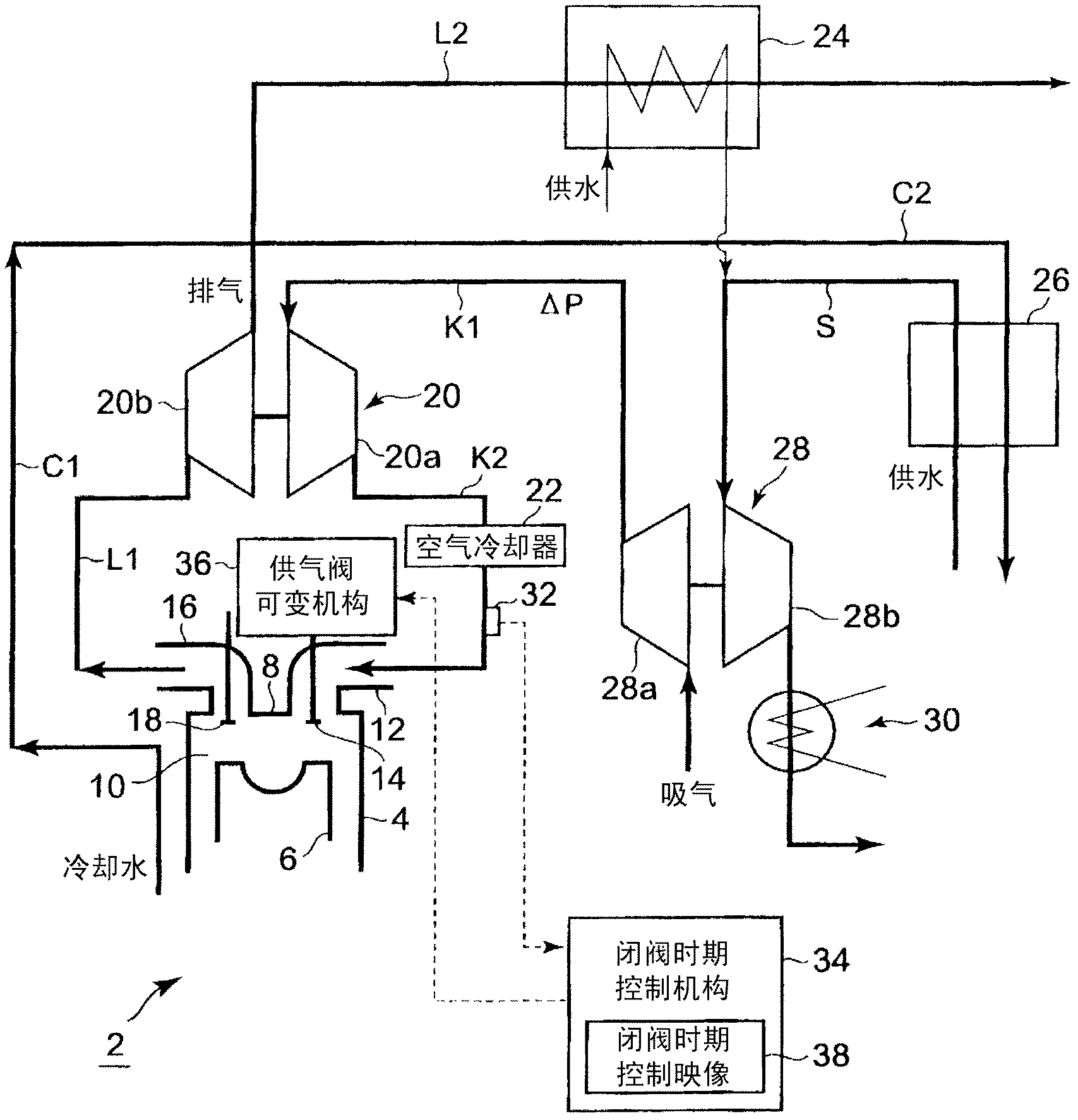
[0042] figure 1 It is an overall configuration diagram of a Miller cycle engine (hereinafter referred to as an engine) 2 according to the first embodiment of the present invention.

[0043] exist figure 1 Herein, the engine 2 is described as an example of a four-stroke gas engine, but it is not limited to the gas engine.

[0044] In the cylinder 4 of the engine main body, there are provided a piston 6 that is reciprocally slidably fitted, and a crankshaft that converts the reciprocating movement of the piston 6 into rotation via a connecting rod not shown, and is provided above the piston 6. A combustion chamber 10 formed between the surface and the inner surface of the cylinder head 8, an air supply port 12 connected to the combustion chamber 10, and an air supply valve 14 for opening and closing the air supply port 12 are also equipped with An exhaust port 16 connected to the chamber 10 and an exhaust valve 18 that opens and closes the exhaust port 16 .

[0045] In addi...

no. 2 approach

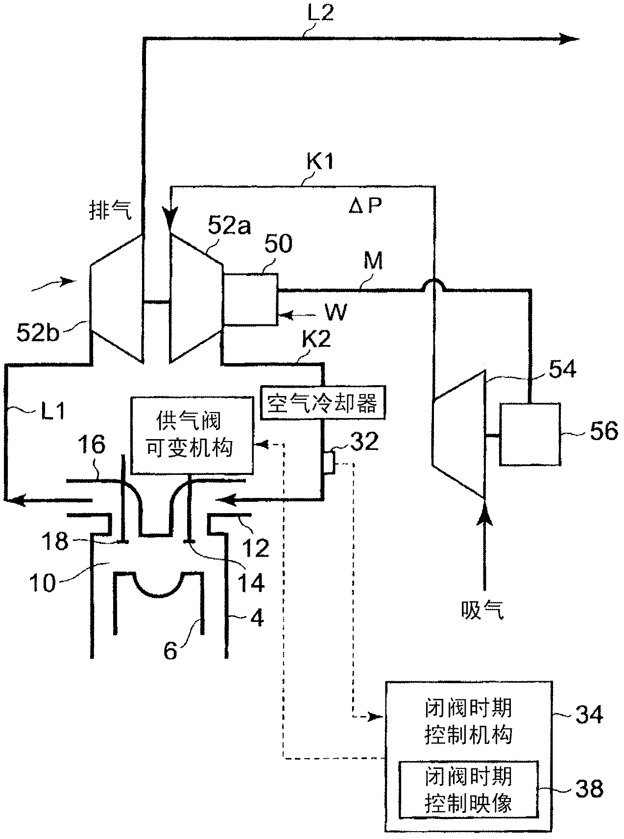
[0071] refer to figure 2 , to describe the second embodiment.

[0072] The second embodiment uses electric power generated by exhaust gas as regenerative energy of the engine.

[0073] Such as figure 2 As shown, the supercharger is composed of a hybrid supercharger 52 with a built-in generator motor 50 , and the air supply blower provided on the air supply passage K1 upstream of the hybrid supercharger 52 is driven by electric power generated by using exhaust gas. 54, thereby generating additional air supply pressure.

[0074]The hybrid supercharger 52 is composed of a compressor unit 52a and a turbine unit 52b, and the generator motor 50 is built in the compressor unit 52a. Power is generated by the rotation of the compressor unit 52a, and the generated power is supplied to the blower motor 56 that drives the air supply blower 54 through the power supply line M. The rotation speed of the blower motor 56 is controlled using an inverter or an increase / decrease gear (not s...

no. 3 approach

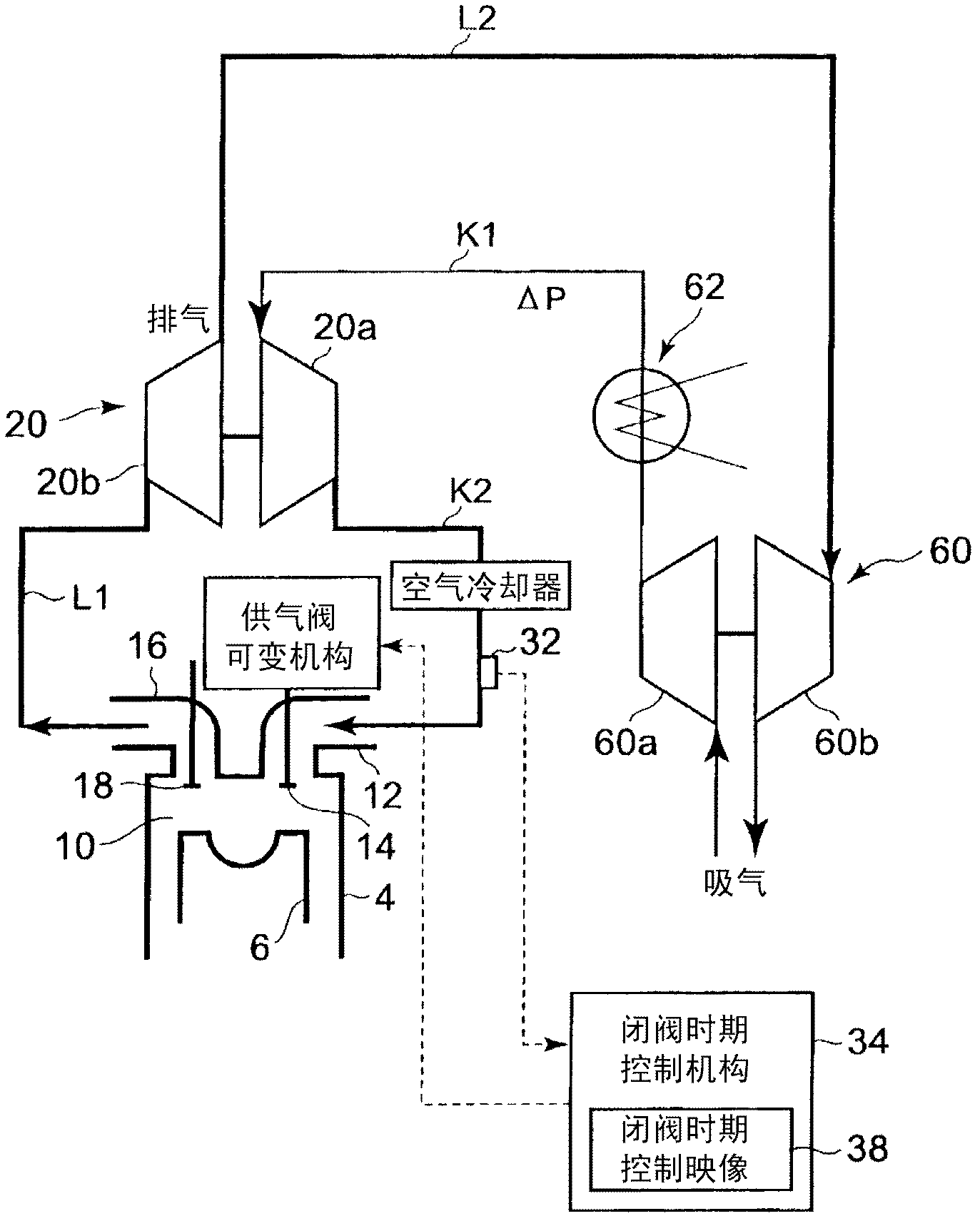
[0079] Next, refer to image 3 , to describe the third embodiment. This third embodiment drives the front-stage supercharger 60 using exhaust gas as regenerative energy of the engine. That is, a precharger 60 is provided instead of the steam turbine 28 described in the first embodiment.

[0080] Such as image 3 As shown, the exhaust gas having passed through the turbine portion 20b of the supercharger 20 flows into the turbine portion 60b of the pre-supercharger 60 to drive the compressor portion of the pre-supercharger 60 coaxially provided with the turbine portion 60b. 60a to pressurize the air supply. In order to supply the pressurized supply air to the compressor section 20a of the supercharger 20 and further pressurize it, the compressed air passes through both the compressor section 60a of the pre-stage supercharger 60 and the compressor section 20a of the supercharger 20. Stage supercharging composition.

[0081] In addition, an air cooler 62 is provided in the ai...


PUM


Abstract

Disclosed is a Miller cycle engine wherein the heat efficiency is improved by increasing the supply air pressure and the reliability of the mechanical strength and thermal load of the engine body is maintained by maintaining the in-cylinder maximum pressure. Specifically disclosed is a Miller cycle engine characterized by being provided with a supply air valve varying means (36) which controls the valve opening / closing time of the supply air valve (14), a stream turbine (28) which serves as a supply air pressure adding device for additionally increasing only the supply air pressure with respect to supercharging by a supercharger (20) or increasing the supply air pressure more than the exhaust air pressure, and a valve closing time control means (34) which advances the valve closing time of the supply air valve (14) further as the supply air pressure added by the steam turbine (28); is higher to thereby maintain approximately the same in-cylinder maximum pressure as the in-cylinder maximum pressure before the addition.

Description

technical field [0001] The invention relates to a Miller cycle engine in which the gas supply valve is closed earlier or later than the bottom dead center so that the compression ratio is smaller than the expansion ratio, and especially relates to a technique for improving the thermal efficiency of the Miller cycle by increasing the gas supply pressure. Background technique [0002] The Miller cycle engine closes the air supply valve earlier or later than the bottom dead center to maintain the compression ratio of the engine smaller than the expansion ratio, thereby avoiding the occurrence of knocking and helping to achieve high thermal efficiency. Furthermore, a large expansion ratio is realized, and the combustion gas is sufficiently expanded so that the combustion energy can be more effectively utilized as torque. [0003] Figure 7 The P-V diagram shown by the solid line is a P-V diagram of an internal combustion engine with a supercharger, and represents a Miller cycle ...

Claims


Application Information

Patent Timeline
Patent Type & Authority Applications(China)
IPC IPC(8): F02D13/02F01K23/06F01K23/10F01N5/02F02B37/00F02D15/00F02D23/00F02G5/00F02G5/02
CPCF02B37/04Y02T10/144F02B41/04Y02T10/12F02D13/0215F02B33/40F02B37/10F01K23/065F02D23/00Y02T10/16F02B2275/32F02D13/0269F02B37/013F02D15/04F01N5/02Y02T10/142F02B29/04F02B29/0406F01K23/06F02D13/02F02D15/00
Inventor 石田道靖小田健次郎长面川升司
Owner MITSUBISHI HEAVY IND ENGINE & TURBOCHARGER LTD
Why Eureka
Try Eureka