Electric impedance imaging system with open electrode scanning mode

A technology of electrical impedance imaging and scanning electrodes, which is applied in the field of biomedical imaging, can solve the problems of inability to obtain useful information, low imaging accuracy, and low imaging resolution, and achieve the goals of increasing useful information, simple structure, and improving resolution Effect

Inactive Publication Date: 2012-07-18
TIANJIN UNIV
View PDF9 Cites 8 Cited by
  • Summary
  • Abstract
  • Description
  • Claims
  • Application Information

AI Technical Summary

Problems solved by technology

However, the current electrical impedance imaging system still faces the status quo of low imaging resolution and low imaging accuracy, which cannot meet the needs of clinical diagnosis
This is because the essence of electrical impedance imaging reconstruction is to solve a nonlinear, underdetermined and ill-conditioned inverse problem through the surface potential (or surface potential difference); most of the current electrical impedance imaging systems use fixed electrode signal excitation and acquisition mode, see figure 1 , taking 16 electrodes as an example, when measuring, the adjacent or opposite electrodes are used as excitation electrodes, and other electrodes are used as measurement electrodes to obtain voltage (or current) information at other 14 positions. This system is limited by the surface area of ​​the imaging body and can be placed The number of electrodes is limited, which makes it difficult to improve the problem of underdetermination; and because most of the measuring electrodes are arranged uniformly, more useful information cannot be obtained in the effective area where the potential changes greatly

Method used


Image

  • Electric impedance imaging system with open electrode scanning mode
  • Electric impedance imaging system with open electrode scanning mode
  • Electric impedance imaging system with open electrode scanning mode

Examples


Embodiment 1

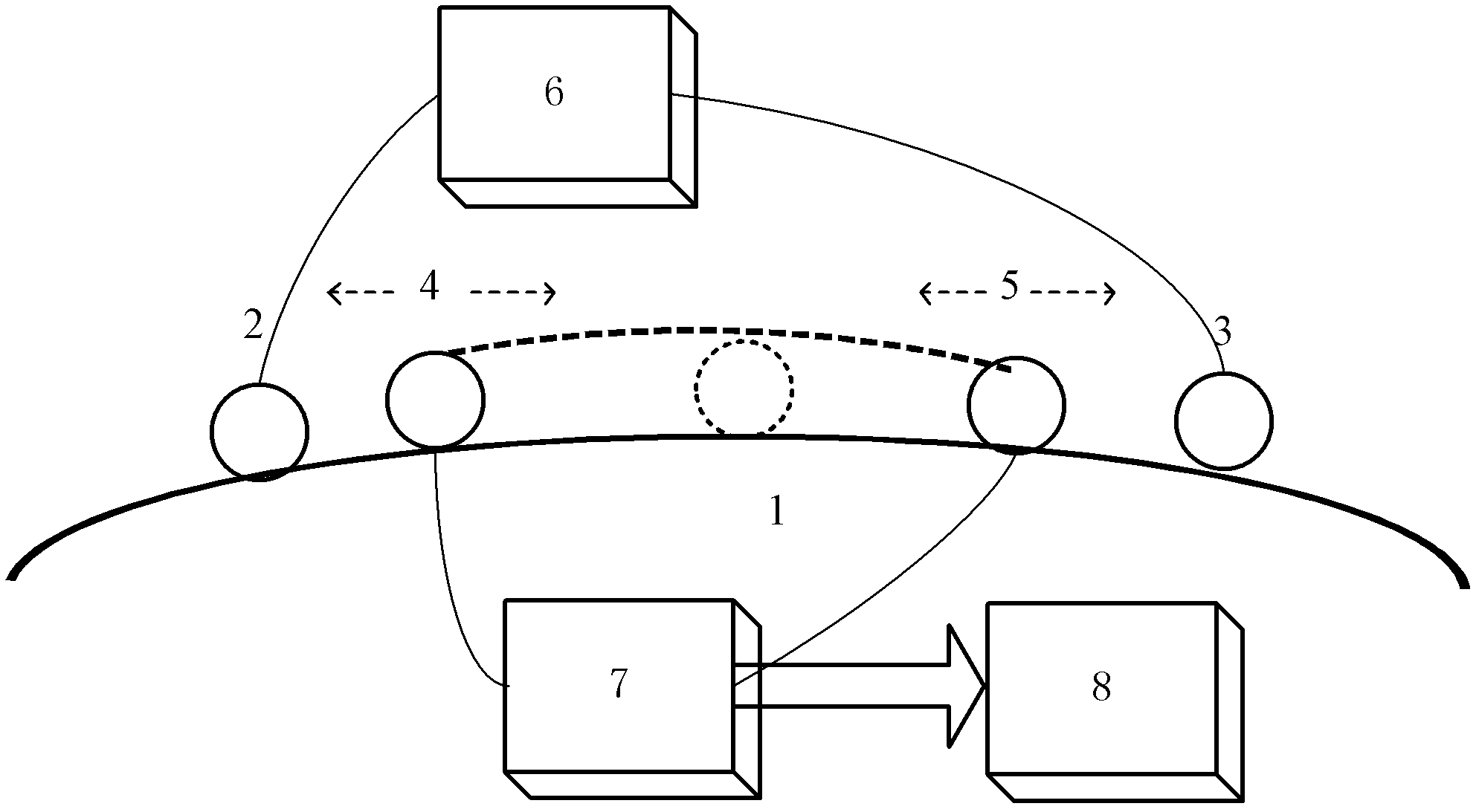
[0049] When the first measurement electrode 4 and the second measurement electrode 5 are double-ended scanning, refer to figure 2 , the excitation signal is a low-frequency current source, which is applied to the imaging body 1 through the excitation electrodes 2 and 3 . The first measurement electrode 4 and the second measurement electrode 5 are located between the two excitation electrodes 2 and 3, both of which are active ends. During measurement, the second measuring electrode 5 moves one unit from the starting position 3 to the ending position 2 along the surface of the imaging body 1, and the first measuring electrode 4 is all along the imaging body 1 surface from the starting position 2 to the ending position 3 (for example: The first measurement electrode 4 starts to move from the position where the excitation electrode 2 is located as the starting position, and moves to the position where the excitation electrode 3 is as the end position) to perform a scan to obtain ...

Embodiment 2

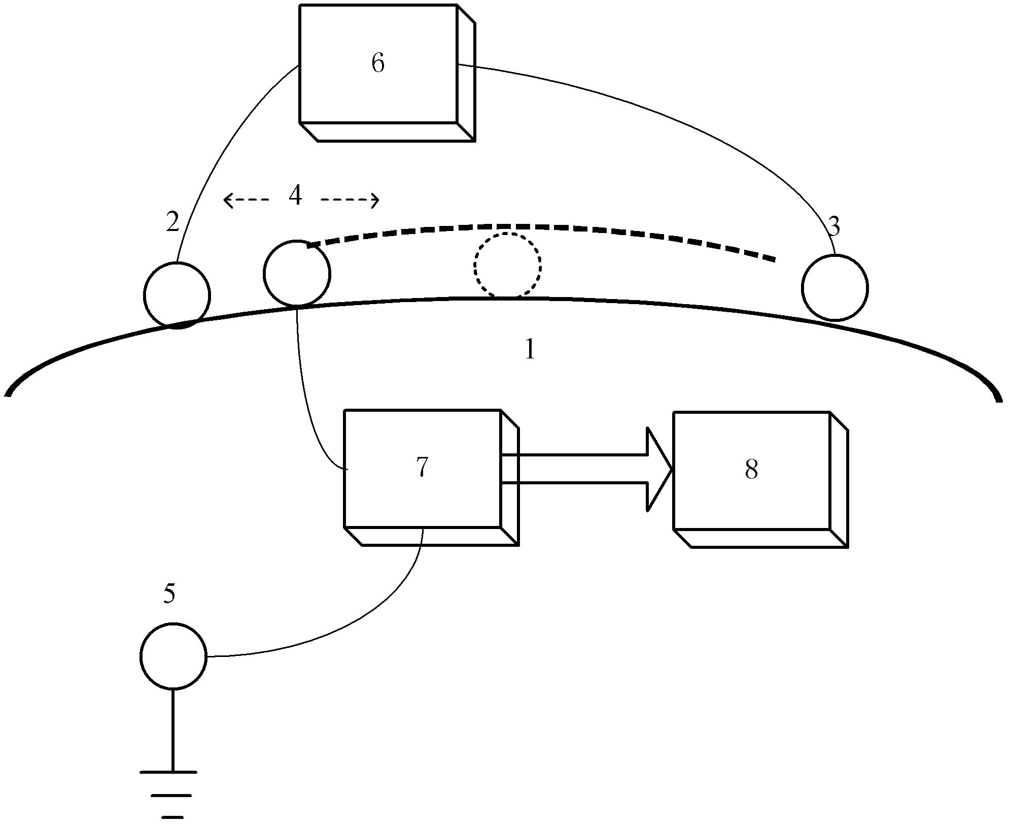
[0051] When the first measuring electrode 4 is single-ended scanning, see image 3 , the excitation signal is a low-frequency current source, which is applied to the imaging body 1 through the excitation electrodes 2 and 3 . The first measurement electrode 4 is located between the two excitation electrodes 2 and 3, the first measurement electrode 4 is a movable end, and the second measurement electrode 5 is fixed at a certain position of the imaging body as a zero potential reference point. During the measurement, the measuring device 7 scans from the starting position 2 to the ending position 3 along the surface of the imaging body 1 by the first measuring electrode 4 (for example: the first measuring electrode 4 starts to move from the position where the excitation electrode 2 is at the starting position, Move to the position where the excitation electrode 3 is located (the end position), to obtain the voltage distribution on the scanning route, the measuring device 7 transm...


PUM


Abstract

The invention discloses an electric impedance imaging system with an open electrode scanning mode. Exciting electrodes introduce an excitation signal emitted from an excitation source into an imaging body; a first measurement electrode and a second measurement electrode carry out one-dimensional or two-dimensional scanning along the surface of the imaging body between the exciting electrodes; a measurement device collects measurement information of the imaging body through the first measurement electrode and the second measurement electrode, and transmits the measurement information to a microprocessor, and the microprocessor processes the measurement information and rebuilds an electric impedance distribution image of the imaging body. According to the electric impedance imaging system disclosed by the invention, limitation of the surface area of the imaging body to the mounting quantity of the first measurement electrode and the second measurement electrode is overcome, the density of arranged measurement electrodes is greatly improved by arrangement of the first measurement electrode and the second measurement electrode; useful information is increased; the ill-condition of rebuilding the electric impedance is improved; the imaging resolution ratio of the electric impedance (or impedance spectroscopy) is improved and the rebuilding quality of the image is also improved.

Description

technical field [0001] The invention relates to the field of biomedical imaging, in particular to an electrical impedance imaging system with an open scanning electrode mode. Background technique [0002] The electrical characteristics of biological tissue can reflect the physiological and pathological information of the organism, as follows: different biological tissues have different electrical impedance characteristics; the impedance of biological tissues changes with physiological activities; there is a gap between the impedance of diseased biological tissues and normal tissues big difference. Electrical impedance imaging, which takes the electrical impedance distribution of biological tissues as the imaging target, has important clinical value in the localization of diseased tissues and early diagnosis of diseases. The principle is to apply a certain safe excitation current (or voltage) to the imaging target, measure the voltage (or current) signal on the surface of th...

Claims


Application Information

Patent Timeline
Patent Type & Authority Applications(China)
IPC IPC(8): A61B5/053
Inventor 李刚陈瑞娟刘近贞郝丽玲林凌
Owner TIANJIN UNIV
Why Eureka
Try Eureka