Jet welding method and jet welding groove

A technology of jet welding and welding tank, applied in welding equipment, tin feeding devices, manufacturing tools, etc., can solve the problems of uneven flux coating and preheating, poor tin penetration, temperature drop, etc. The probability of copper exceeding the standard is reduced, the tin dross is easy to handle, and the effect of saving power resources

Inactive Publication Date: 2012-07-18
SHENZHEN KUNQI XINHUA
View PDF5 Cites 25 Cited by
  • Summary
  • Abstract
  • Description
  • Claims
  • Application Information

AI Technical Summary

Problems solved by technology

[0008] In view of the current wave soldering and selective wave soldering processes encountered in flux coating and uneven preheating, temperature drop, intermittent soldering, continuous soldering, sharpening, empty soldering, poor tin penetration, soldering shadow effects, etc. For the problem of through-hole...

Method used


Image

  • Jet welding method and jet welding groove
  • Jet welding method and jet welding groove
  • Jet welding method and jet welding groove

Examples


Embodiment 1

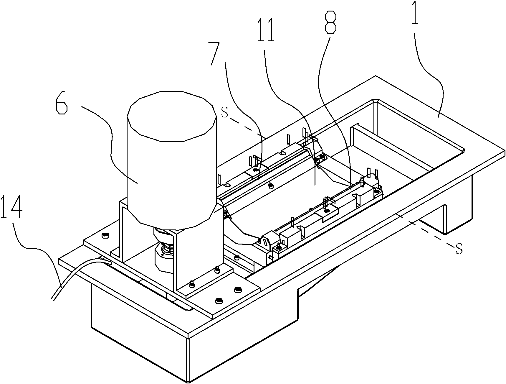
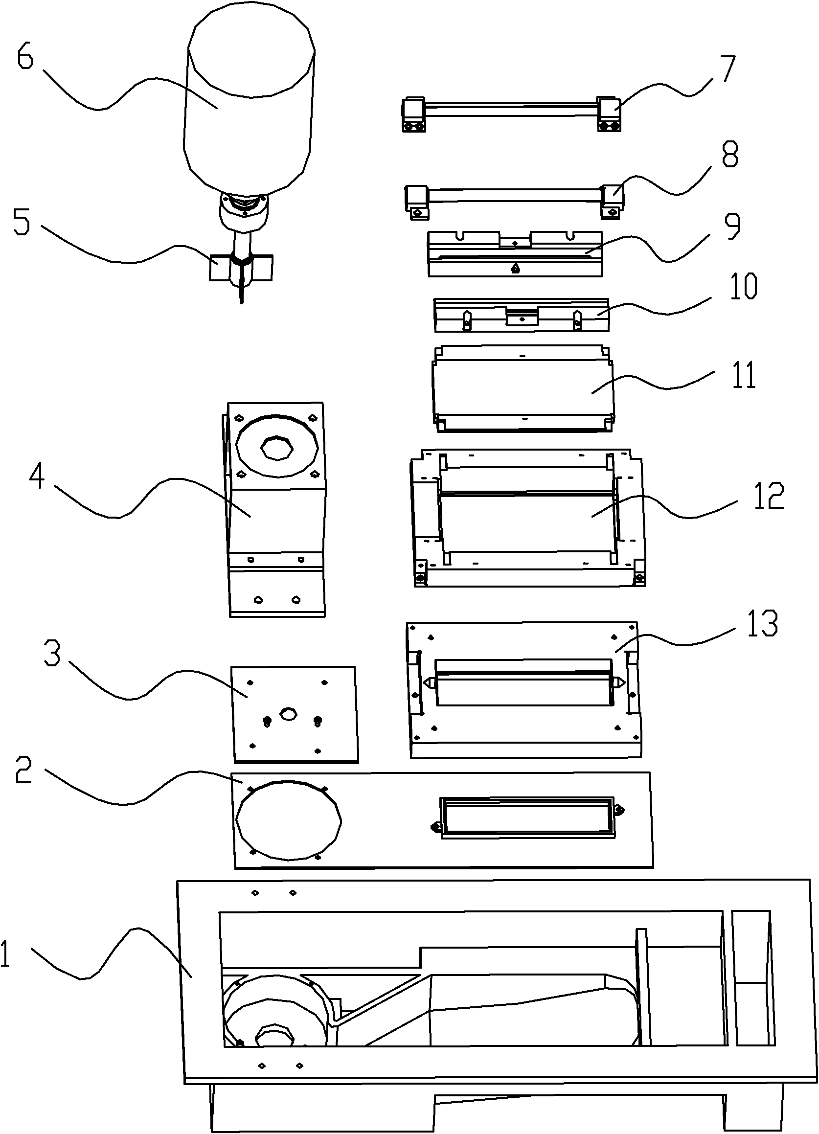
[0036] Such as figure 2 , image 3 , Figure 4 , Figure 5 , Figure 6 , a jet flow welding tank for realizing the above jet flow welding, comprising a welding tank 1, the welding tank 1 is divided into a welding chamber 103, a reducing agent addition chamber 105 and a high second medial partition 106 by a low first longitudinal partition 104 and a high second longitudinal partition 106. Waste recovery chamber 107, welding chamber 103 ends have a sunken circular solder chamber 101, and solder chamber 103 has a sunken strip-shaped solder passage 102 connected to the circular solder chamber 101 rising toward the first longitudinal partition plate 104 direction; welding chamber 103 There is a passage cover 2 on the upper cover, and the passage cover 2 is provided with a circular hole with a size similar to that of the circular solder chamber 101 above the circular solder chamber 101, and a hole smaller than the strip solder passage 102 is provided at the top of the strip sold...

Embodiment 2

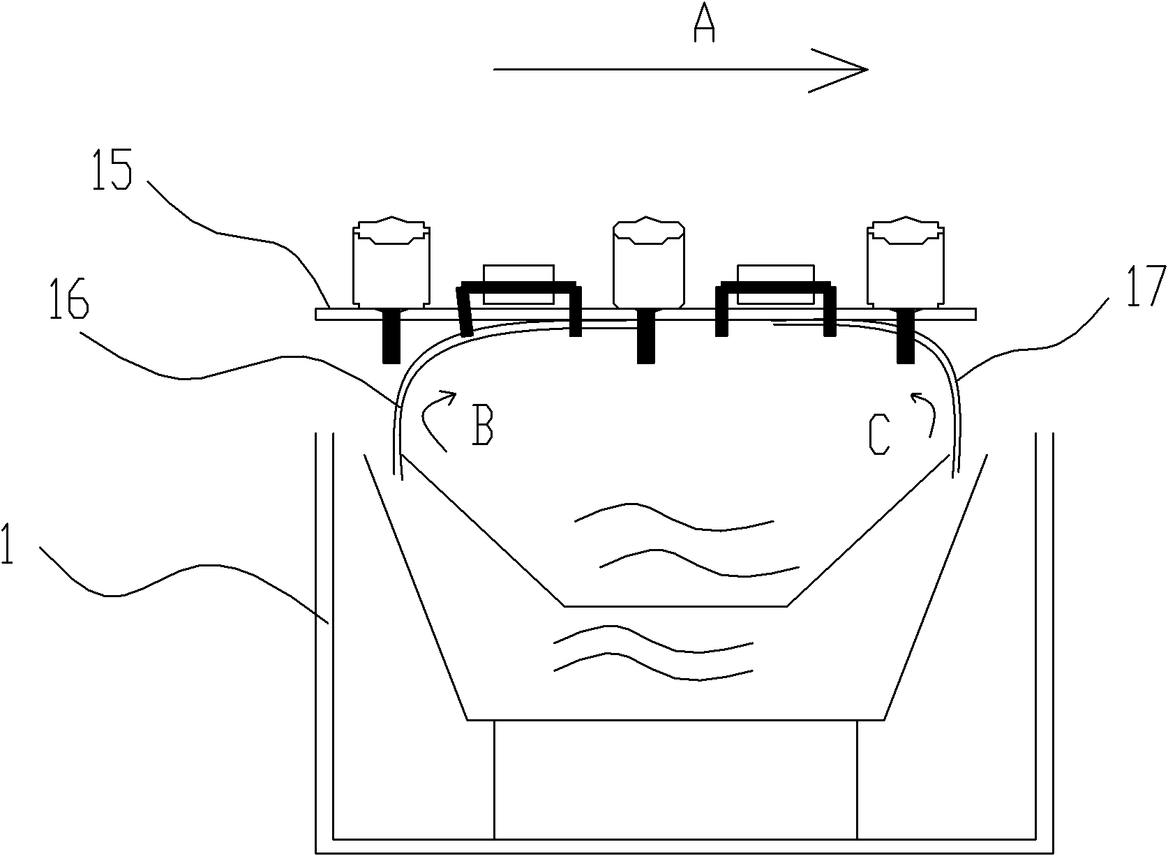
[0038] Such as Figure 7 , another spray flow welding tank for realizing the above spray flow welding. The difference from Embodiment 1 is that a third longitudinal septum 110 is designed above the strip-shaped solder channel 102 close to the junction of the pressurized diverter fixing seat 12, A fifth longitudinal partition 108 is designed above the junction of the circular solder chamber 101 and the strip-shaped solder channel 102. The tops of the third longitudinal partition 110 and the fifth longitudinal partition 108 are level with the edge of the welding tank 1, and the bottom is flush with the edge of the soldering groove 1. The bottom of the tank 1 is separated; a fourth longitudinal septum 109 is designed in the middle of the third longitudinal septum 110 and the fifth longitudinal septum 108, the bottom of the fourth longitudinal septum 109 is in close contact with the upper surface of the strip-shaped solder channel 102, and the top is low at the edge of the weld gr...


PUM

PropertyMeasurementUnit
Widthaaaaaaaaaa

Abstract

The invention relates to a welding process for a PCB (printed circuit board), and discloses a jet welding method, which includes the process steps of flux spraying, preheating and welding. The process step of welding adopts a jet welding process, which is characterized in that melted welding flux is sprayed out of two opposite elongated nozzles parallelly arranged on two sides of a welding groove by the aid of a mechanical pump or an electromagnetic pump, and forms two obliquely upward opposite parabolic liquid surfaces contacting with the surface of the PCB in a parabolic manner. The invention further discloses a jet welding groove using the jet welding method. The jet welding method and the jet welding groove have the advantages that automation of a through hole welding process and through hole welding quality can be effectively improved, electric power resources and tin resources are saved, and production cost can be reduced for electronic manufacturers.

Description

technical field [0001] The present invention relates to the welding process of PCB boards, in particular to a jet flow welding that can effectively improve the automation of the through-hole welding process, the quality of the through-hole welding and reduce the production cost, and a jet flow welding bath that realizes the jet flow welding process . Background technique [0002] With the development of electronic products in the direction of miniaturization and multi-function, electronic components are getting smaller and smaller, and the assembly density is getting denser and denser. Most electronic products are gradually replaced by surface mount technology (reflow soldering process). hole welding process. [0003] However, in most of the electronic components (connectors, etc.) or electronic products (military supplies, servers, etc.) Still need to use through-hole (TH) soldering process; such as TV sets, home audio-visual equipment, and digital set-top boxes to be lau...

Claims


Application Information

Patent Timeline
IPC IPC(8): B23K1/00B23K3/06H05K3/34
Inventor 严永农
Owner SHENZHEN KUNQI XINHUA
Why Eureka
Try Eureka