Dual-station pneumatic stamping machine

A punching machine, double station technology, applied in punching machines, presses, manufacturing tools, etc., can solve the problems of not meeting the punching force, wasting energy, limiting the application of punching machines, etc., to achieve convenient operation, simple and compact structure, The effect of high energy efficiency

Inactive Publication Date: 2012-07-18
SUZHOU UNIV
View PDF4 Cites 22 Cited by
  • Summary
  • Abstract
  • Description
  • Claims
  • Application Information

AI Technical Summary

Problems solved by technology

However, the system pressure generated by pneumatic transmission is generally 0.4 ~ 0.7Mpa, which is far from meeting the stamping force required by the stamping process. This requires increasing the volume of the cylinder to provide the required stamping force, which seriously limits the stamping machine. Applications
In addition, for a single-station stamping machine, after the stamping is completed, the reverse stroke of the cylinder piston is an empty stroke, which wastes energy

Method used


Image

  • Dual-station pneumatic stamping machine
  • Dual-station pneumatic stamping machine
  • Dual-station pneumatic stamping machine

Examples


Embodiment Construction

[0019] The technical solutions of the present invention will be further described below in conjunction with the accompanying drawings and specific embodiments.

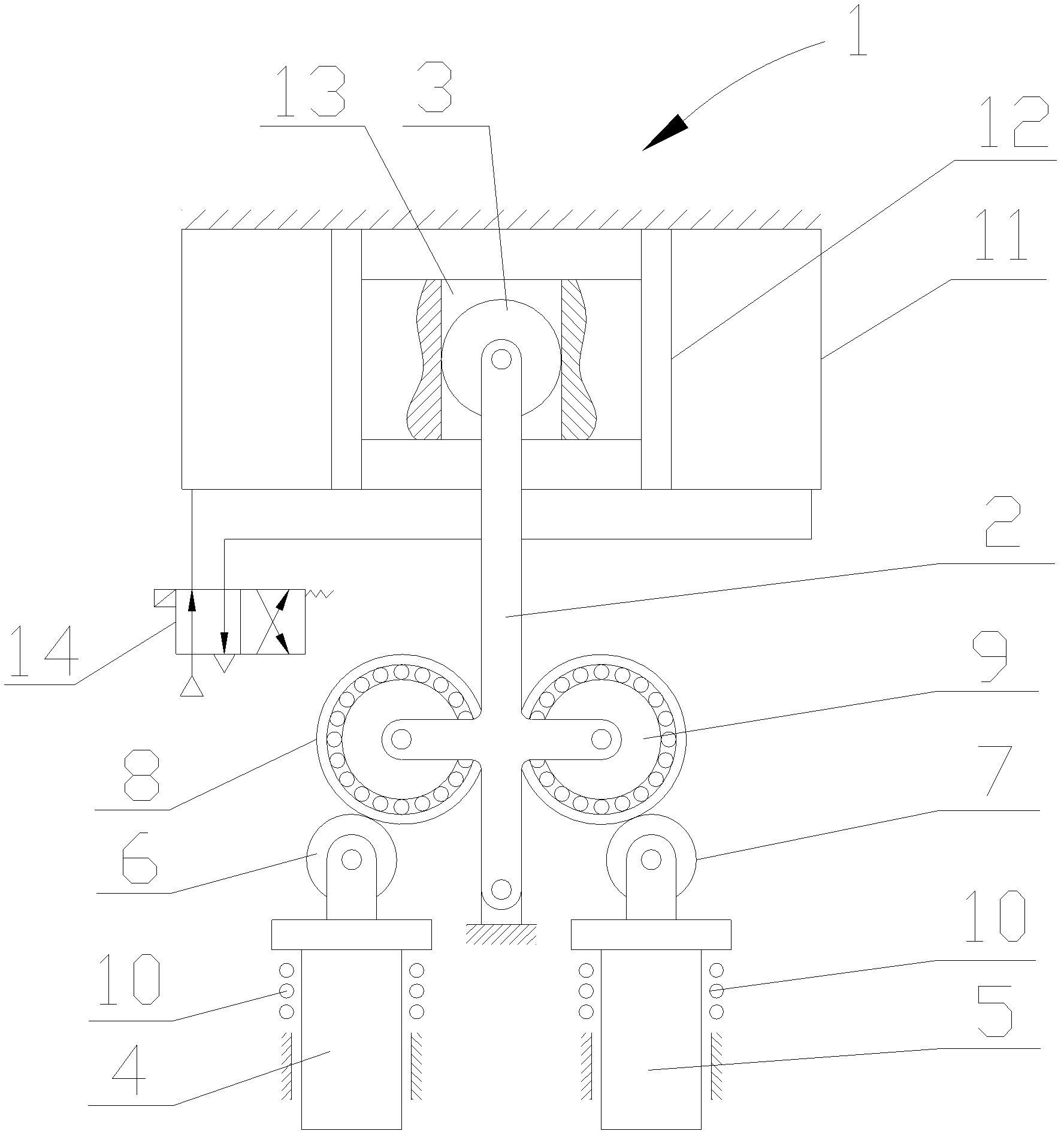
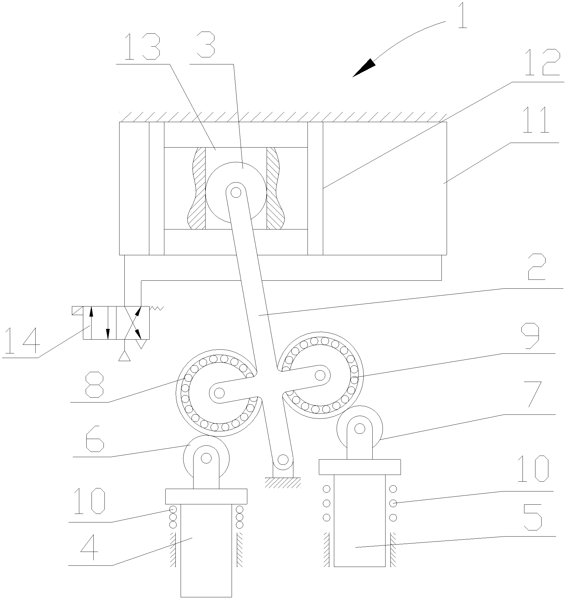
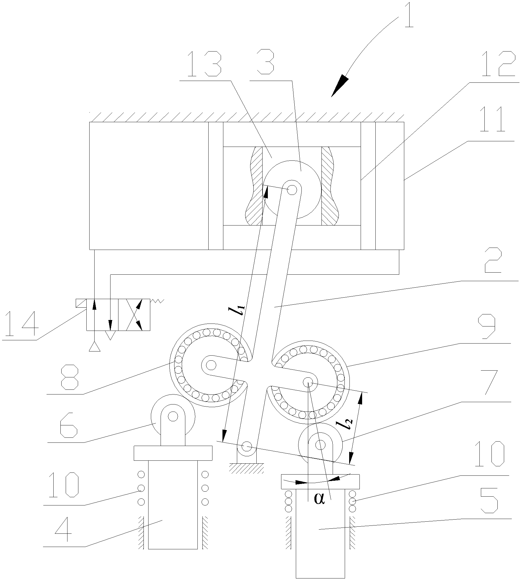
[0020] see Figure 1-3 As shown, a double-station pneumatic punching machine includes a double-acting cylinder 1, and the double-acting cylinder 1 includes a cylinder 11 and a piston 12 arranged in the cylinder 11 and capable of moving along its axial direction, wherein the piston 12 is sealed with the cavity wall of the cylinder 11 and divides the inner cavity of the cylinder 11 into two parts, the cylinder 11 is fixedly connected and arranged on the frame, and the axis of the cylinder 11 extends along the horizontal left and right directions. The pneumatic stamping machine also includes a lever 2, the lower end of the lever 2 is rotatably connected to the frame, the upper end of the lever 2 is rotatably connected to a slider 3, and the piston 12 is provided with a slider 3 that can be used for the slider 3 along...


PUM


Abstract

The invention discloses a dual-station pneumatic stamping machine, which is provided with a double-acting cylinder serving as a power source. A lever capable of swinging along with movement of a piston of the double-acting cylinder is disposed on a frame, and a roller which is capable of matching with upper rollers on stamping heads in transmission is disposed on the lever. When the double-acting cylinder is in operation, the piston continuously moves side by side inside a cylinder barrel, so that the first stamping head on the left of the lever and the second stamping head on the right of the lever are alternately operated in stamping. Idle stroke is absent in operation of the dual-station pneumatic stamping machine, stamping output force is approximately as large as acting force outputted by a piston rod of a medium-pressure hydraulic transmission system, the stamping efficiency is high, and the energy utilization rate is high. In addition, the dual-station pneumatic stamping machine is simple and compact in structure, convenient in operation and highly economical. Pneumatic transmission is used as the power source, so that operation of the machine is pollution-free, and the dual-station pneumatic stamping machine is widely applicable to stamping.

Description

[0001] technical field [0002] The invention relates to a double-station pneumatic punching machine. [0003] Background technique [0004] At present, the society advocates green energy saving, which requires people to use low-energy, low-consumption, and low-pollution power sources to complete work in actual production. The power source of the stamping machine in the project mostly adopts hydraulic transmission and pneumatic transmission. The pressure of the hydraulic transmission system is high and the output force is large, but the energy utilization rate of the hydraulic system is low, the noise of the hydraulic pump is relatively large, and it is easy to cause environmental pollution due to oil leakage and volatilization. Pneumatic transmission uses clean compressed air as the working medium, does not cause environmental pollution, and has a fast piston movement speed and high production efficiency. It is more and more widely used in the field of mechanical enginee...

Claims


Application Information

Patent Timeline
Patent Type & Authority Applications(China)
IPC IPC(8): B30B1/08
Inventor 高新新郭旭红钟康民黄星徐青山
Owner SUZHOU UNIV
Why Eureka
Try Eureka