Electric-hydro complex brake system employing integral brake master cylinder assembly

A brake master cylinder, electro-hydraulic composite technology, applied in the direction of brake transmission, brake, transportation and packaging, can solve problems such as increasing hydraulic source, achieve easy processing, improve braking efficiency, and flexible pedal feel design. Effect

Inactive Publication Date: 2012-07-18
TONGJI UNIV
View PDF4 Cites 40 Cited by
  • Summary
  • Abstract
  • Description
  • Claims
  • Application Information

AI Technical Summary

Problems solved by technology

Some systems use hydraulic assist, but a

Method used


Image

  • Electric-hydro complex brake system employing integral brake master cylinder assembly
  • Electric-hydro complex brake system employing integral brake master cylinder assembly
  • Electric-hydro complex brake system employing integral brake master cylinder assembly

Examples


Embodiment

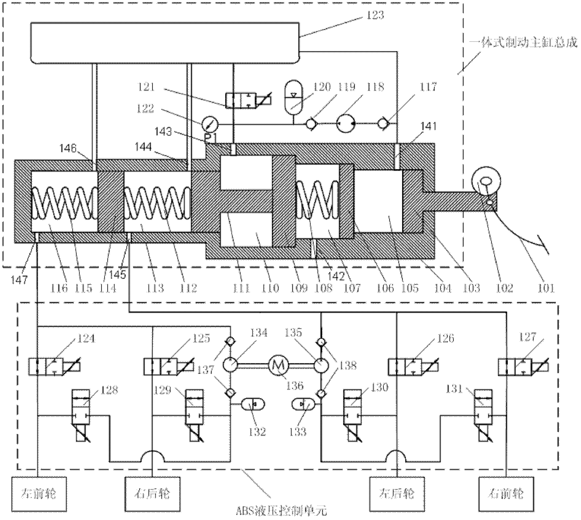
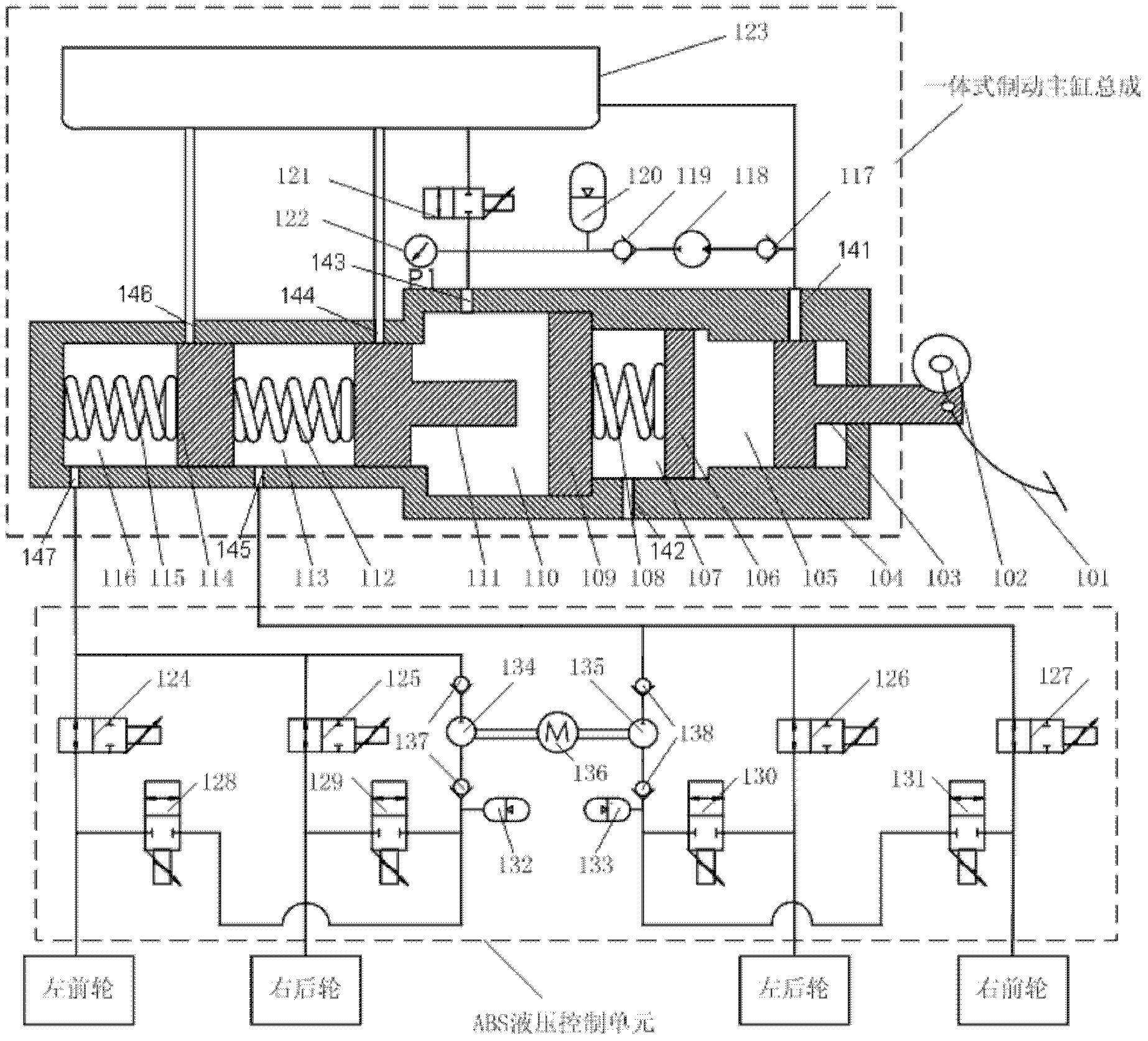
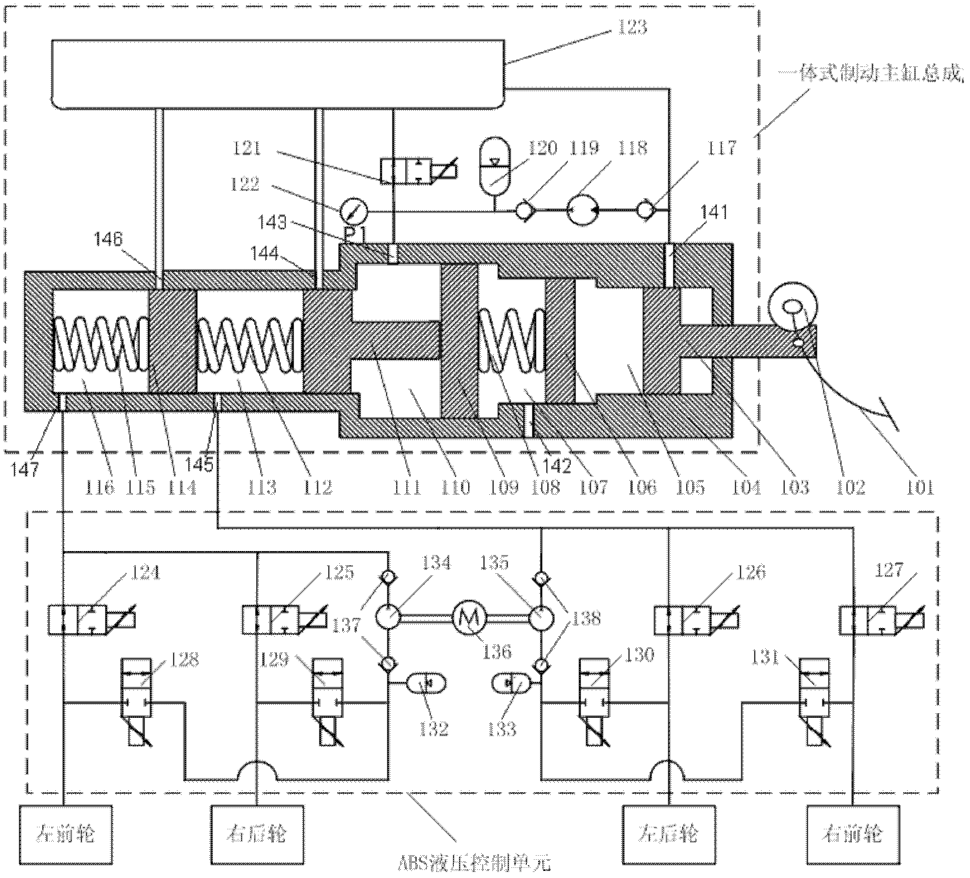
[0032] Such as figure 1 As shown, it is a schematic diagram of the present invention in the initial state, the master cylinder push rod 104 of the integrated brake master cylinder assembly, the first booster piston 107, the second booster piston 110, the first master cylinder piston 112, the second master cylinder The two pistons 115 are at the far right side under the action of the first return spring 112, the second return spring 115 and the pedal feeling simulation spring 108, i.e. the initial position; The cylinder rear chamber 114 and the master cylinder front chamber 117 communicate with the liquid storage chamber 123 through the first through hole 141, the third through hole 143, the fourth through hole 144 and the sixth through hole 146 on the cylinder body 104 respectively. The chamber 114 and the front chamber 117 of the master cylinder communicate with the two input ports of the ABS hydraulic control unit through the fifth through hole 145 and the seventh through ho...


PUM


Abstract

The invention relates to an electric-hydro complex brake system employing an integral brake master cylinder assembly for vehicle, including: a brake pedal, a pedal displacement sensor, an integral brake master cylinder assembly and an ABS hydraulic control unit, which are in turn connected. The ABS hydraulic control unit is connected with brake wheel cylinders of four wheels of the vehicle. Compared with the prior art, in a state that the electric system of the vehicle does not work, the hydraulic pressure inside the integral brake master cylinder assembly assists a first chamber to amplify the input force of the push rod of the master cylinder, and a pedal simulation spring drives and assists a second piston, a first piston for the master cylinder and a second piston for the master cylinder, in order to form the pressure required by braking.

Description

technical field [0001] The invention relates to an automobile brake system, in particular to an electro-hydraulic composite brake system adopting an integral brake master cylinder assembly. Background technique [0002] During the braking process of new energy vehicles, while the mechanical hydraulic braking force is applied to the wheels, the drive motor can work in the power generation state to apply regenerative braking force to the wheels, so that the braking energy can be recovered and stored in the vehicle while effectively braking the vehicle. Energy storage equipment can be reused to improve the energy utilization efficiency, fuel economy and emission performance of new energy vehicles. [0003] The participation of regenerative braking force in braking can facilitate the recovery of braking energy, but it also brings some problems, mainly including flexible, precise and fast control of brake line pressure, optimization of driver's pedal feeling, optimization of NVH ...

Claims


Application Information

Patent Timeline
IPC IPC(8): B60T8/36B60T13/68
CPCB60T8/441B60T8/4275
Inventor 孙泽昌王猛
Owner TONGJI UNIV
Why Eureka
Try Eureka