Primary dedusting system for rotating furnace

A dust removal system and converter technology, applied in the direction of manufacturing converters, improving process efficiency, improving energy efficiency, etc., can solve the problems of long maintenance time, excessive dust emission rate, high cost, etc., and achieve simple structure and low dust emission rate , low cost effect

Inactive Publication Date: 2012-07-18
BAOSHAN IRON & STEEL CO LTD
View PDF1 Cites 0 Cited by
  • Summary
  • Abstract
  • Description
  • Claims
  • Application Information

AI Technical Summary

Problems solved by technology

[0012] 1. The cost of dry dust removal is high, and there are many automatic control chains, which require a high degree of automation
[0013] 2. Many mechanical equipments are used, the structure is complex, the failure rate is high, and the maintenance time is long
[0014] 3. The gas temperature is high after dust removal, and it must be cooled by a special cooling system before entering the gas cabinet
However, the current converter dedusting system either has a dust emission rate exceeding the standard, or is complex in structure and expensive in cost.

Method used


Image

  • Primary dedusting system for rotating furnace
  • Primary dedusting system for rotating furnace
  • Primary dedusting system for rotating furnace

Examples


Embodiment

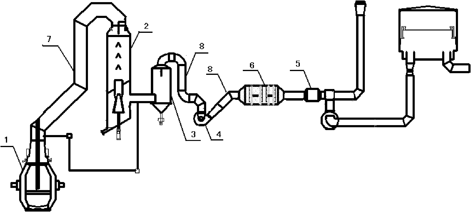
[0028] Such as figure 1 As shown, it is a structural schematic diagram of a primary dust removal system for a converter according to the present invention. The dust removal system includes a converter 1, a spray cooling tower 2, an annular seam washing tower 3, a dehydrator 4 and a fan 5. The gas in the converter 1 passes through the vaporization flue 7 to the spray cooling tower 2, and then passes through the gas in turn. The pipeline 8 leads to the ring seam washing tower 3, the dehydrator 4 and the fan 5, and the dust removal system also includes a dehumidifier 6, which is connected in series between the outlet of the dehydrator 4 and the inlet of the fan 5. Preferably, the dehumidifier is a cylindrical horizontal dehumidifier. This facilitates manufacture, installation and maintenance.

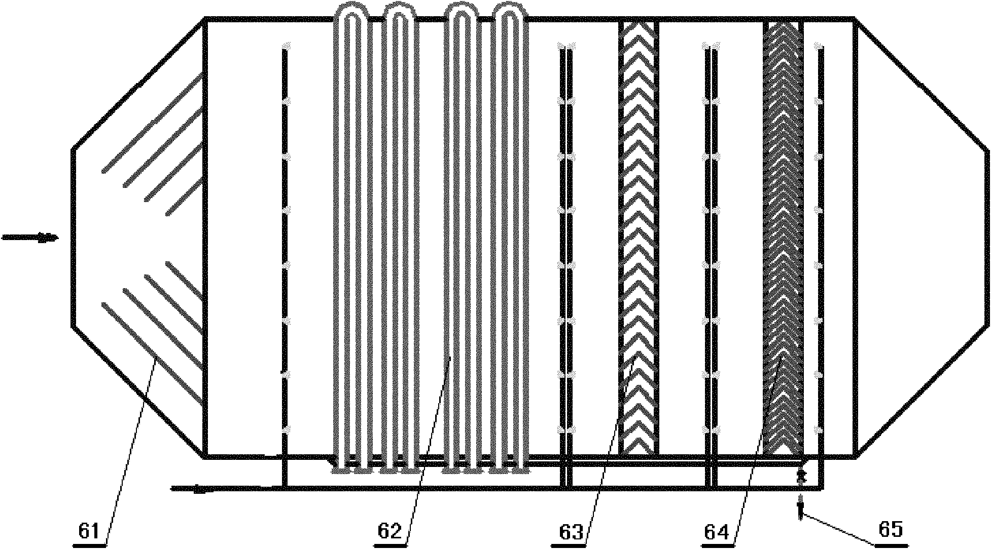
[0029] Such as figure 2 Shown is a schematic structural view of the dehumidifier in the dust removal system. The dehumidifier is provided with an inlet section, a condensation section...


PUM


Abstract

The invention relates to a primary dedusting system for a rotating furnace. The dedusting system comprises the rotating furnace, a spray cooling tower, a ring seam scrubbing tower, a dehydrator and a fan, wherein the coal gas in the rotating furnace is filled into the spray cooling tower through an evaporation flue, and is then sequentially filled into the ring seam scrubbing tower, the dehydrator and the fan through coal gas pipelines; the dedusting system also comprises a dehumidifier which is connected between the dehydrator and the fan in series; and one end of the dehydrator is connected with an outlet of the dehydrator, and the other end of the dehydrator is connected with an inlet of the fan. The primary dedusting system for the rotating furnace not only has lower dust emission rate, but also is simple in structure and lower in cost.

Description

technical field [0001] The invention relates to the field of industrial furnace flue gas treatment and dust removal, in particular to a primary dust removal system applied in the converter steelmaking process of metallurgical steel plants. Background technique [0002] In the metallurgical industry, a large amount of smoke and dust will be produced during the steel smelting process. In order to ensure that the environment is not polluted, it is necessary to control the emission of smoke and dust. Generally, a high-power dust removal fan is used to optimize the operation control of the smelting process, so that harmful smoke After being purified by the dust removal system, it is discharged to achieve the purpose of reducing air pollution and improving air quality. [0003] Converter dust removal includes three parts: primary dust removal, secondary dust removal and post dust removal. The primary dust removal system directly affects the recovery and utilization of converter ga...

Claims


Application Information

Patent Timeline
Patent Type & Authority Applications(China)
IPC IPC(8): C21C5/40
CPCY02P10/25
Inventor 黄建东邬志君郁祖达
Owner BAOSHAN IRON & STEEL CO LTD
Why Eureka
Try Eureka