Sampling device for exhaust particles of engine

A sampling device and engine technology, which is applied in the direction of exhaust device, electric control of exhaust treatment device, engine components, etc., can solve the problem that the amount of particle sampling does not meet the requirements of particle analysis, the experimental workload and energy waste, and the continuous filter paper cannot be realized. Replacement and other issues, to achieve the effect of reducing the experimental workload, simple structure, and low cost

Active Publication Date: 2012-07-18
XIHUA UNIV
View PDF6 Cites 6 Cited by
  • Summary
  • Abstract
  • Description
  • Claims
  • Application Information

AI Technical Summary

Problems solved by technology

This sampling method has the following disadvantages: (1) Since the concentration of particles decreases after the exhaust gas is diluted, the sampling amount of particles usually does not meet the requirements of particle analysis; (2) The dilution of the gas flow will cause changes in the characteristics of particles to a certain extent , resulting in errors in the analysis of particle characteristics; (3) The existing filter paper installation device can only achieve one-time collection, and cannot realize continuous replacement of filter paper; due to the engine operating point to be studied according to the experimental requirements, it is necessary to frequently start and stop the sampling system , Dismantling the device to replace the filter paper, resulting in a huge experimental workload and energy waste

Method used


Image

  • Sampling device for exhaust particles of engine
  • Sampling device for exhaust particles of engine
  • Sampling device for exhaust particles of engine

Examples


Embodiment Construction

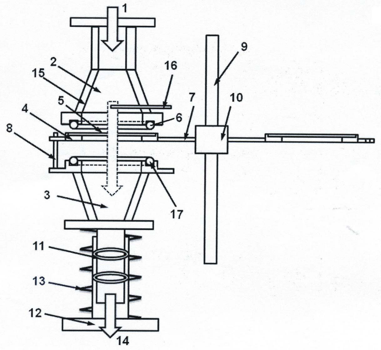
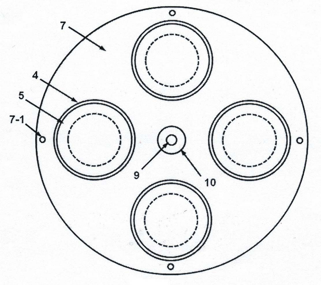
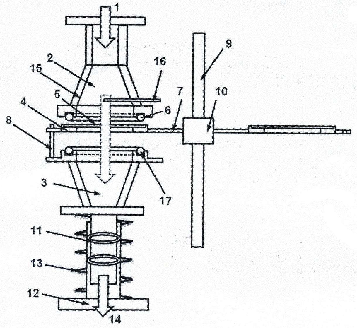
[0022] figure 1 Middle: 1. Entrance; 2. Upper cover; 3. Lower cover; 4. Filter paper mounting plate; 5. Filter paper; 6. Upper cover filter paper O-ring seal; 7. Turntable; 8. Positioning pin; 9. Fixed shaft; 10. Bearing; 11. O-shaped sealing ring; 12. Base casing; 13. Spring; 14. Outlet; 15. (upper and lower cover) heating insulation layer; 16. Temperature sensor. 17. O-ring of filter paper under the cover.

[0023] figure 1 It is shown that the engine exhaust particulate sampling device is fixed on the frame with the upper cover 2 used to introduce engine exhaust gas, and the upper cover filter paper O-ring 6 is arranged in the groove on the lower end surface of the upper cover to discharge the engine The lower cover 3 of the exhaust gas is located directly below the upper cover, the pipe section at the lower part of the lower cover extends into the base sleeve 12 in a sliding fit, and an O-ring 11 is arranged between the lower pipe section of the lower cover and the base sleev...


PUM


Abstract

The invention relates to a sampling device for exhaust particles of an engine. The sampling device is characterized in that a lower cover is arranged inside a casing pipe of a base and can move up and down; an upper cover and the lower cover are automatically compacted by springs; and filter paper installing plates are arranged between the upper cover and the lower cover. When the springs are compressed, the upper cover, the filter paper installing plates and the lower cover are sealed; exhausts of the engine inflow, the exhaust particles are filtered by filter paper, and the exhausts outflowthrough the lower cover and the casing pipe of the base; the multiple filter paper installing plates are arranged on the same turntable; the turntable can rotate around a fixing shaft parallel to themiddle axes of the upper cover and the lower cover; when a certain amount of particles are collected, the springs are compressed again so as to lead the upper cover, the filter paper installing plates and the lower cover from being separated; the turntable is rotated so that the installing plates, in which clean filter paper is placed, are rotated between the upper cover and the lower cover; and after the springs are loosened, the filter paper sealing is realized again for carrying particle sampling. The sampling device has the characteristics of having simple structure, being convenient to operate and being capable of realizing the online connection and replacement of the filter paper.

Description

Technical field [0001] The invention belongs to an engine exhaust gas post-processing sampling device, and in particular relates to a device for filtering and sampling engine exhaust particles by using filter paper. Background technique [0002] At present, the particulate matter emitted by automobiles is the main source of inhalable particulate matter in the atmosphere. The reduction of exhaust particulates from vehicle engines and meeting the requirements of emission regulations are one of the key technical issues that the engine industry urgently needs to solve. The particulate matter emitted by the engine is formed by the aggregation of tiny carbon-based particles with a diameter of about 25 nm, which are produced by incomplete combustion of fuel, forming aggregates of various diameters and shapes. The particle size is mainly distributed in 100 nm~300 nm. In the range. The particles in this range are all particles that can enter the lung. Carbon-based particles adsorb a lay...

Claims


Application Information

Patent Timeline
Patent Type & Authority Applications(China)
IPC IPC(8): F01N3/021F01N11/00
CPCY02T10/47Y02T10/40
Inventor 孟忠伟干平彭俊涵杨冬康朝国
Owner XIHUA UNIV
Why Eureka
Try Eureka