U-shaped capacitive liquid level meter

A technology of capacitive and liquid level gauges, which is applied in the direction of liquid level indicators for physical variable measurement, etc., can solve the problems of not working properly, large changes in dielectric coefficient, non-sticky insulating coating, etc., and achieve excellent electrical performance , Measuring stable, non-toxic, physiologically inert effect

Inactive Publication Date: 2012-07-18
南宁测控自动化科技有限公司
View PDF9 Cites 2 Cited by
  • Summary
  • Abstract
  • Description
  • Claims
  • Application Information

AI Technical Summary

Problems solved by technology

After investigation and testing, it was found that most of the electrodes could work normally to complete the measurement in the initial stage, but after some time, there were also many problems that the product could not overcome
The key is that the insulating coating of the insulating electrode is too fragile, and it is extremely easy to be damaged during the installation process, and it also faces the test of temperature, pressure, crystallization and other fusions during use. Cleaning, and the electrode insulation coating can not withstand such a harsh environment at all, and the electrode leakage often occurs during use and cannot work normally.
In addition, the insulating coating is not non-sticky, which is affected by the adhesion of molasses, and the measurement results are greatly affected
However, the materials used for electrodes using insulating sleeves are ordinary materials, and the dielectric coefficient changes greatly with temperature changes, which also directly affects the measurement results.
Similarly, the insulating sleeve is not non-stick, and the measurement results are greatly affected by the adhesion of molasses.
In particular, some insulating sleeves use a plugging method to seal the end of the insulating sleeve. Under the condition of temperature and pressure fusion, the sealing will not be lost for a long time, and then the electrode leakage will also occur.

Method used


Image

  • U-shaped capacitive liquid level meter
  • U-shaped capacitive liquid level meter
  • U-shaped capacitive liquid level meter

Examples


Embodiment Construction

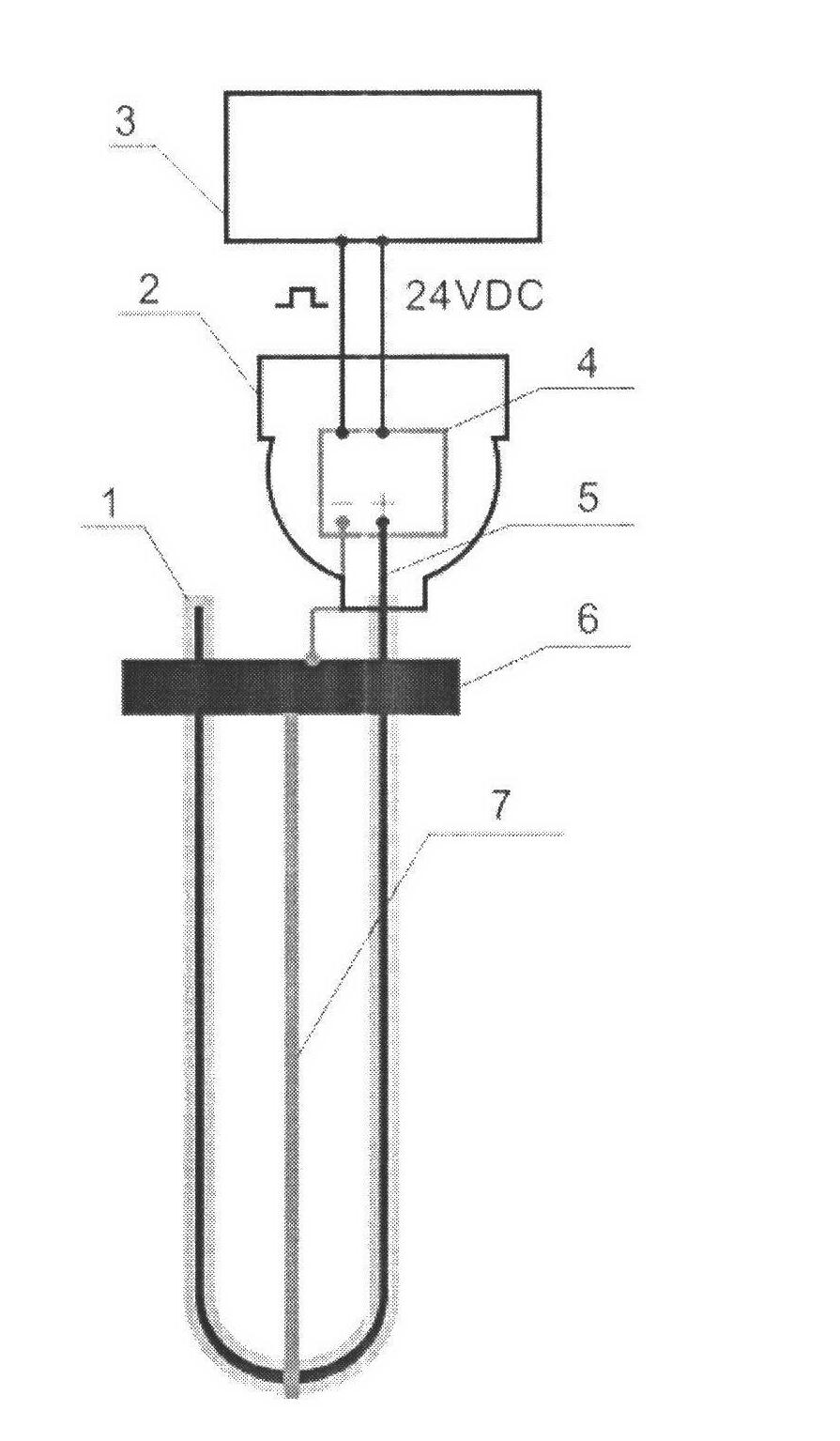
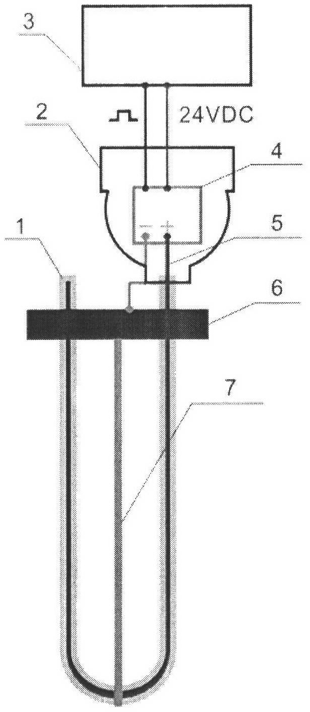
[0020] 1. Structural composition of a U-shaped capacitive liquid level gauge

[0021] The inner electrode 5 and the electrode insulating outer sleeve 1 have a U-shaped structure, the inner electrode 5 is inserted into the electrode insulating outer sleeve 1, the electrode insulating outer sleeve 1 is made of polytetrafluoroethylene material, the inner electrode 5 and the outer electrode 7 are made of stainless steel, When the present invention is applied, both ends of the inner electrode 5 are outside the container for measuring materials.

[0022] 2. Working principle of a U-shaped capacitive liquid level gauge

[0023] The inner electrode 5 with an insulating jacket is used as the positive pole of the capacitor, and the outer electrode 7, the metal tank shell of the container for measuring the material and the material are used as the negative pole, and the two together form a capacitor. As the liquid level of the material changes and the relative area of ​​the capacitance ...


PUM


Abstract

The invention discloses a U-shaped capacitive liquid level meter, which is composed of an electrode insulation outer sleeve, a transmitter casing, a displayer, a transmitter circuit, an inner electrode, a flange and an outer electrode. The transmitter circuit is composed of a power supply circuit, a pulse output circuit, a phase step time integrating circuit and an RC phase step circuit. The U-shaped capacitive liquid level meter has the advantage that 1 the electrode sleeve adopts the U-shaped structure in design, the changing area is twice that of pole type sleeve, and measurement is led tobe stable and accurate; and 2 the liquid level meter adopts a Teflon pipe with good performance as a material, the material has the advantages of high temperature resistance, abrasion resistance, weather resistance, high lubrication, non-adhesiveness, non-toxicity and excellent electric performance, and the liquid level meter can perfectly and completely measure liquid level under the effects of temperature, pressure fusion, molasses adhesion, molasses adhesion and scale deposition even the dielectric parameter is affected by temperature.

Description

technical field [0001] The invention relates to a material liquid level measuring device. Specifically, it is a U-shaped capacitive liquid level gauge. Background technique [0002] At present, the measurement of the liquid level of the evaporation tank in the sugar factory adopts the principle of differential pressure. Due to the unstable pressure and temperature in the evaporation tank, and the constant change of the sugar liquid hammer during the evaporation process, coupled with the influence of fouling, the liquid level measurement is inaccurate. , Seriously affect the DCS control system of the evaporation process. [0003] The current capacitive liquid level transmitters are all used in occasions with good working environment. Therefore, it is no problem to use it in other industrial occasions, but it has to face many restrictions on the limit of use in occasions with harsh conditions. Such as the measurement of the liquid level of the evaporation tank of the sugar ...

Claims


Application Information

Patent Timeline
Patent Type & Authority Applications(China)
IPC IPC(8): G01F23/26
Inventor 梁支信
Owner 南宁测控自动化科技有限公司
Why Eureka
Try Eureka