
Method and system for imaging spectrum

A spectral imaging and aperture technology, applied in the field of spectral imaging, can solve the problems of reducing the light energy usage rate of the imaging system, data loss, and existence of distortion, etc., and achieve the suppression of system imaging quality degradation, avoiding size deviation, and easy control of aberrations Effect

Inactive Publication Date: 2014-02-26
SUZHOU UNIV
View PDF6 Cites 0 Cited by
  • Summary
  • Abstract
  • Description
  • Claims
  • Application Information

AI Technical Summary

Problems solved by technology

[0004] Even if some technical limitations of traditional spectral imaging are overcome, various new spectral imaging methods still have their own problems: Computational tomography imaging technology requires a focal plane of a very large area array to collect tomographically compressed data images, And there is a problem of missing data; in the aperture-coded staring spectral imaging technology, the three-dimensional spectral data cube of the shooting scene reconstructed from the single-frame sampling data takes a lot of time and has distortion; the image folding spectral imager is limited by technology, and currently it can Very limited number of bands reached
To sum up, the new spectral imaging method has the following deficiencies: 1. The three-dimensional spectral data cube restored by compressed imaging is distorted, and the spectral images and spectral curves of each band of the scene cannot be accurately obtained; 2. The number of imaging devices is large, reducing the The light energy utilization rate of the imaging system is limited, and the system structure is complex, which is not conducive to the miniaturization of the imaging system; 3. It takes a lot of time to reconstruct the spectral data, and it is impossible to realize the synchronous processing of the spectral data after shooting, and thus cannot achieve high frame rate spectral imaging
However, there is no relevant report on its application in spectral imaging.

Method used


Image

  • Method and system for imaging spectrum
  • Method and system for imaging spectrum

Examples


Embodiment

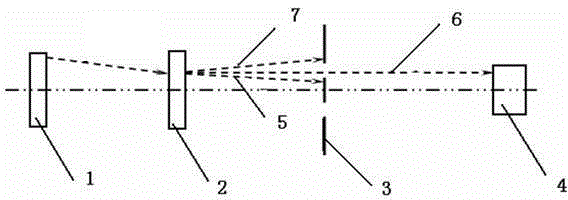
[0023] See attached figure 1 , the spatial light modulator 2 is placed at an appropriate position directly in front of the shooting target 1, and by setting the shape of the modulation unit on it, the modulation surface forms concentric ring-shaped Fresnel wave bands with different pitches and widths, alternating light and dark slice pattern. The aperture 3 is placed between the shooting target 1 and the detector 4, and the function of the aperture 3 is to filter out the zeroth order diffracted light 5 and other order diffracted rays 7 generated by the zone plate pattern of the spatial light modulator 2, while Only the image of the first-order diffracted light 6 generated by the zone plate pattern of the spatial light modulator is projected and focused on the focal plane of the detector 4 .

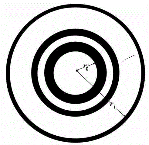
[0024] See attached figure 2 , which is a schematic diagram of parameter construction of the zone plate pattern set by the spatial light modulator in this embodiment. The zone plate p...


PUM


Abstract

The invention discloses a method and a system for imaging a spectrum. The optical system comprises a space optical modulator generating a zone plate with different patterns, wherein a detector is arranged at the equivalent focal plane of the zone plate, and a diaphragm is arranged between a shooting target and the detector, so that the first stage of diffraction image generated by a fresnel zone plate can be acquired on the focal plane of the detector, and the other stages of the diffraction images not for acquiring can be filtered out. The method for imaging the spectrum comprises the following steps of: generating n zone plates with different patterns, and respectively focusing images with different wave lengths of the shooting target on the focal plane of the detector, to obtain the spectrum image with different wave lengths of the shooting target. After the building parameters of the zone plate are changed, the spectrum image with each waveband of scenery to be shot can be directly obtained on an appointed image surface without brooming in a pushing way. The system is simple to build, the aberration is easy to control, and the original spectrum data with each waveband of the scenery to be shot can be directly obtained, so that the data is high in fidelity.

Description

technical field [0001] The invention relates to a spectral imaging technology, in particular to a wavelength-scanning spectral imaging method and system thereof. Background technique [0002] Spectral imaging technology can obtain a three-dimensional spectral data cube with two-dimensional space and one-dimensional spectrum of the captured scene. Since its birth in the 1980s, it has been widely used in atmospheric monitoring, resource surveying, forest protection, medical diagnosis and other fields. Traditional spectral imaging can be divided into three categories: wavelength scanning, spatial scanning and time scanning. Wavelength-scanning spectral imaging uses tunable filter devices such as optical filters and acousto-optic modulators to realize the band selection of the scene, and acquires a spectral image of a certain band of the scene for each shot. Several shots can obtain its multi-band spectral image acquisition. The spectral imaging band range and the number of ba...

Claims


Application Information

Patent Timeline
Patent Type & Authority Patents(China)
IPC IPC(8): G01J3/28G01J3/02G02B5/18
Inventor 陈宇恒季轶群周建康陈新华曾文明沈为民
Owner SUZHOU UNIV
Learn More