Check patentability & draft patents in minutes with Patsnap Eureka AI!

Circuit and method for sampling excitation inductance current of integrated transformer

A technology that integrates transformers and excitation inductances. It is used in the measurement of current/voltage, instruments, and electrical variables. It can solve the problems of increasing the additional loss of the acquisition circuit and the inability to sample the current of the excitation inductance of the transformer, so as to achieve a simple structure and reduce losses. Effect

Inactive Publication Date: 2012-07-18
NANJING UNIV OF AERONAUTICS & ASTRONAUTICS
View PDF4 Cites 9 Cited by
  • Summary
  • Abstract
  • Description
  • Claims
  • Application Information

AI Technical Summary

Problems solved by technology

However, none of these existing methods can be used to sample the excitation inductor current of a transformer integrated with an output filter inductor.
For the measurement of the excitation current of the integrated transformer, the traditional method is to connect the resistance in series with the leakage inductance, and use the resistance voltage to reflect the excitation inductance current. The resistance voltage measured by this method includes the secondary winding current of the integrated transformer generated on the resistance. The voltage component cannot directly measure the exciting inductor current, and this method increases the additional loss of the acquisition circuit

Method used


Image

  • Circuit and method for sampling excitation inductance current of integrated transformer
  • Circuit and method for sampling excitation inductance current of integrated transformer
  • Circuit and method for sampling excitation inductance current of integrated transformer

Examples


Embodiment Construction

[0014] Below in conjunction with accompanying drawing, the technical scheme of invention is described in detail:

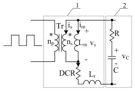
[0015] Such as figure 1 As shown in the sampling circuit of the excitation inductance current of the integrated transformer, the integrated transformer 1 includes: the primary winding, the secondary winding, and the excitation inductance L m , DC resistance DCR, leakage inductance L r . Exciting inductance L m , DC resistance DCR, leakage inductance L r sequentially connected in series. Exciting inductance L m connected in parallel at both ends of the secondary winding. The sampling circuit 2 of the integrated transformer excitation inductance current includes a resistor R and a capacitor C connected in series. Integrating the sampling circuit 2 of the excitation inductance current of the transformer and the excitation inductance L m , DC resistance DCR, leakage inductance L r The series circuits formed are connected in parallel. no p is the number of t...


PUM


Abstract

The invention discloses a circuit and a method for sampling an excitation inductance current of an integrated transformer, belonging to the technical field of power and electronics. The integrated transformer comprises a primary winding, a secondary winding, an excitation inductor, a DC resistor and a leakage inductor; the excitation inductor, the DC resistor and the leakage inductor are sequentially connected in series; the excitation inductor is connected in parallel at two ends of the secondary winding; the sampling circuit comprises a resistor and a capacitor which are connected in series; the circuit for sampling the excitation inductance current of the integrated transformer is connected in parallel with a series circuit, consisting of the excitation inductor, the DC resistor and the leakage inductor in the integrated transformer. With adoption of the sampling method disclosed by the invention, the measured capacitance voltage is linearly proportional to the excitation inductance current, and the value of the linear ratio is the resistance of the DC resistor. The sampling circuit provided by the invention can be used for reducing loss of measuring an output current in a low-voltage high-current occasion; the sampling circuit has a simple structure, the variation of the excitation inductance current can be timely traced through sampling the voltage of the capacitor on the circuit, and the variation of the excitation inductance current can be directly reflected.

Description

technical field [0001] The invention relates to a sampling circuit and a sampling method for the excitation inductance current of an integrated transformer, belonging to the technical field of power electronics. Background technique [0002] The rapid development of the information industry not only provides a huge market and rapid development momentum for the power supply industry, but also puts forward higher and higher requirements for the volume, weight, efficiency, output dynamic performance and system reliability of the power supply device. . Power magnetic components are widely used in power electronic devices. They are responsible for the transmission, storage, filtering and electrical isolation of magnetic energy, and occupy a large proportion of the volume of power devices. The magnetic integration technology is conducive to the reduction of the volume and weight of the magnetic components and the reduction of the loss of the magnetic parts, which is of great sign...

Claims


Application Information

Patent Timeline
IPC IPC(8): G01R19/00
Inventor 金科顾玲
Owner NANJING UNIV OF AERONAUTICS & ASTRONAUTICS
Features
  • R&D
  • Intellectual Property
  • Life Sciences
  • Materials
  • Tech Scout
  • Unparalleled Data Quality
  • Higher Quality Content
  • 60% Fewer Hallucinations
Learn More