Self-excitation push-pull converter

A self-excited push-pull converter technology, applied in the field of DC-DC or DC-AC converters, can solve the problems of wasting electric energy, poor adaptability of working voltage, shortened life, etc.

Active Publication Date: 2012-07-18
MORNSUN GUANGZHOU SCI & TECH
View PDF6 Cites 23 Cited by
  • Summary
  • Abstract
  • Description
  • Claims
  • Application Information

AI Technical Summary

Problems solved by technology

[0013] 1. Poor working voltage adaptability
[0014] 2. Poor anti-surge performance
[0020] That is, the self-excited push-pull converter of the traditional technology and the self-excited push-pull converter with the application number 201110200894.5, when the operating voltage ris...

Method used


Image

  • Self-excitation push-pull converter
  • Self-excitation push-pull converter
  • Self-excitation push-pull converter

Examples


no. 1 example

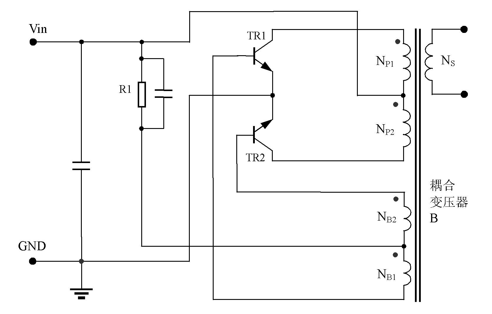
[0060] Figure 8 For the first embodiment, such as Figure 8 As shown, it is a complete self-excited push-pull converter using a constant current source with negative resistance characteristics as a bias, and the main topology of the circuit is a Royer circuit.

[0061] In order to expound its working principle of the first embodiment of the present invention conveniently, first describe the working principle of the constant current source of negative resistance characteristic in the circuit, the constant current source of negative resistance characteristic is made up of voltage detection circuit, constant current source, output circuit; Voltage detection circuit The positive and negative input terminals of the voltage and output circuit are respectively connected to the positive and negative phases of the input power supply; one end of the constant current source is connected to the positive or negative of the input power supply, and the other end of the constant current sour...

no. 2 example

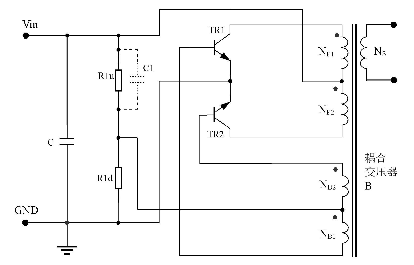
[0103] Figure 15 For the second embodiment, a negative resistance characteristic constant current source INR1 is between the DC loop of the base of the push-pull switching triode and the effective power supply terminal. The difference from the first implementation is that the Figure 8 Capacitor C51, changed to Figure 15 The mid-span is connected between the center tap of the feedback winding of the self-excited push-forward converter and the ground to improve Figure 8 When the working voltage of the circuit is high, the impact of the capacitor C51 on the push-pull switching transistor when the power is turned on.

[0104] like Figure 15 As shown, it is not only possible to achieve Figure 8 At the same time, since C1 is connected to the ground wire, the capacitor C1 is no longer like Figure 8 Like the middle capacitor C51, there is an inrush current to the base and emitter of the triode. On the contrary, in this implementation, since the voltage across the capacitor...

no. 3 example

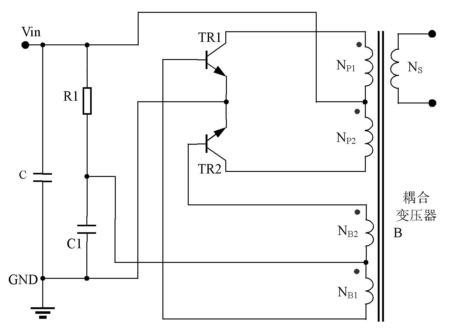
[0107] Figure 16 For the third embodiment, between the DC loop of the base of the push-pull switching transistor and the effective power supply terminal is a constant current source INR1 with negative resistance characteristics, which is corresponding to the prior art image 3 innovative inventions.

[0108] The working principle of the circuit of the third embodiment is: the negative resistance constant current source INR1 replaces the original bias resistor R1, but the current direction is the same, when Figure 16 When the operating voltage of the self-excited push-pull converter increases for some reason, due to the existence of the negative resistance characteristic constant current source INR1, the current provided to the base of TR2 of the two push-pull transistors TR1 is reduced until it is turned off. Observe the collector current of one of the triodes for comparison. When using the existing technology, as the operating voltage increases, the required saturation cur...


PUM

PropertyMeasurementUnit
Capacitanceaaaaaaaaaa

Abstract

The invention discloses a self-excitation push-pull converter. A negative resistance characteristic constant current source is arranged between a direct-current circuit of a base electrode of a push-pull switch triode and an effective power supply end; when the work voltage of the negative resistance characteristic constant current flow is lower than a rated work voltage, higher constant current is provided; when the work voltage of the negative resistance characteristic constant current source is higher than the rated work voltage, the lower constant current is provided; when the work voltage of the negative resistance characteristic constant current source is same as the rated work voltage, the rated constant current is provided; and when the work voltage of the negative resistance characteristic source is constant, and the load changes, the output current of the negative resistance characteristic constant current source is constant. According to the self-excitation push-pull converter, when the work voltage rises, the no-load work current does not rise or descend, when the surges exist in the input voltage of the self-excitation push-pull converter, the switch triode can not be damaged, and when long-time surge voltage exists in the input voltage, the self-excitation push-pull converter of a circuit has certain surge resisting capacity.

Description

technical field [0001] The invention relates to a DC-DC or DC-AC converter, in particular to a self-excited push-pull converter used in industrial control and lighting industries. Background technique [0002] The existing self-excited push-pull converter, the circuit structure comes from the self-excited oscillating push-pull transistor single-transformer DC converter invented by G.H.Royer in 1955, which is also the beginning of realizing high-frequency conversion control circuit; some circuits From the self-excited push-pull double transformer circuit invented by Jen Sen in the United States in 1957, it was later called the self-oscillating Jensen circuit; these two circuits are collectively referred to as the self-excited push-pull circuit pull converter. Self-excited push-pull converters are described on pages 67 to 70 of "Principles and Design of Switching Power Supplies" published by Electronics Industry Press, and the ISBN number of this book is 7-121-00211-6. The m...

Claims


Application Information

Patent Timeline
IPC IPC(8): H02M7/538H02M3/337
Inventor 王保均郑凌霄
Owner MORNSUN GUANGZHOU SCI & TECH
Why Eureka
Try Eureka