
Three-dimensional metal-based Printed Circuit Board (PCB) assembly structure, corresponding light-emitting lamp and manufacturing method

A technology for PCB circuit boards and metal-based circuit boards, which is applied in three-dimensional rigid printed circuit boards, printed circuit manufacturing, and structural connection of printed circuits. ability, limit the design and manufacture of light-emitting lamps, etc., to achieve the effect of facilitating mass mechanized production, improving assembly stability and mechanical strength, and convenient and fast processing

Inactive Publication Date: 2012-07-18
蔡子丰
View PDF6 Cites 12 Cited by
  • Summary
  • Abstract
  • Description
  • Claims
  • Application Information

AI Technical Summary

Problems solved by technology

[0005] The light-emitting device itself consumes electric energy, and the efficiency of electro-optical conversion will not be 100%, there will always be a part of it that will be turned into heat energy, and because the interior of the shell is mostly sealed, the heat cannot be released in time
[0006] Therefore, the heat dissipation problem of the whole lamp has always been a technical bottleneck, and in order to obtain better heat conduction and heat dissipation effects in the prior art, many LED lamps have applied a metal base as the substrate of the PCB circuit board, and for many light emitting diodes For lighting products, light-emitting diodes (LEDs) are usually attached to metal-based PCB (MC-PCB) circuit boards through automated surface-mounting equipment. Therefore, in the surface-mounting process, it is necessary to ensure that the metal-based PCB circuit board is the same A plane (flat), which is why in the vast majority of LED light-emitting lamps in the prior art, the LED components must be attached to the flat PCB circuit board surface, or multiple independent flat The reason why the PCB circuit boards are assembled together into a three-dimensional structure can achieve multi-directional or all-round lighting effects
[0007] At the same time, in the prior art, there is a technical solution of using flexible and bendable PCB circuit boards in LED lighting fixtures. Although this can achieve the characteristics of lighting in multiple directions, because most flexible PCB circuit boards have elasticity and Toughness, but it lacks the necessary rigidity and strength. After bending, it must be given the necessary constraints before it can be shaped. Therefore, complex free-form shapes cannot be realized, and it cannot provide large thermal load capacity, which greatly limits the design of luminous lamps. and manufacturing, it is impossible to achieve low-cost omni-directional lighting

Method used


Image

  • Three-dimensional metal-based Printed Circuit Board (PCB) assembly structure, corresponding light-emitting lamp and manufacturing method
  • Three-dimensional metal-based Printed Circuit Board (PCB) assembly structure, corresponding light-emitting lamp and manufacturing method
  • Three-dimensional metal-based Printed Circuit Board (PCB) assembly structure, corresponding light-emitting lamp and manufacturing method

Examples


Embodiment Construction

[0039] In order to understand the technical content of the present invention more clearly, the following examples are given in detail.

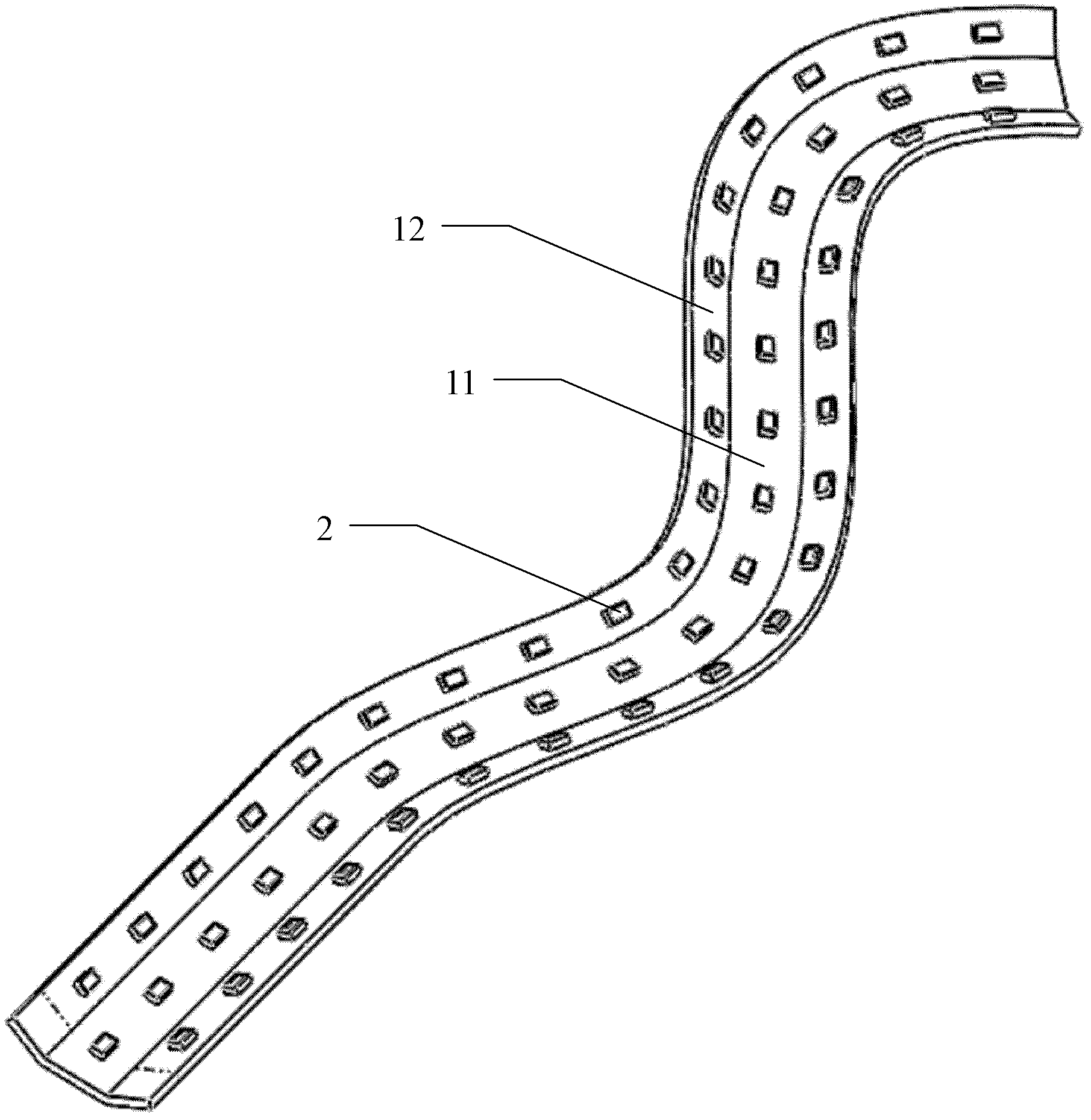
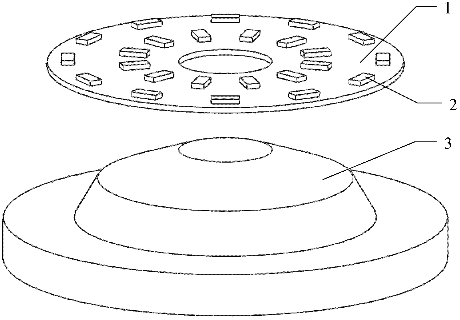
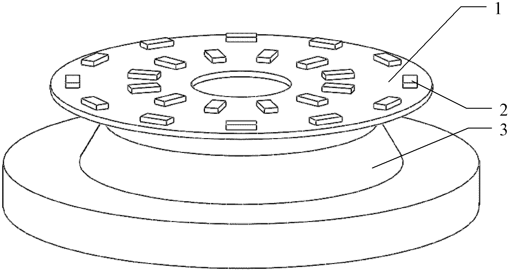
[0040] see figure 1As shown, the three-dimensional metal-based PCB circuit board assembly structure in the light-emitting lamp, wherein the assembly structure consists of a single continuous metal-based circuit board 1 and several light-emitting elements 2 arranged on the upper surface of the metal-based circuit board 1 Each light-emitting element 2 mentioned above is connected to the metal-based circuit board 1, and the parts of the metal-based circuit board 1 with the light-emitting elements 2 are not on the same plane or on the same continuous curved surface, and the metal The base circuit board 1 has a three-dimensional structure.

[0041] Among them, the metal-based circuit board includes:

[0042] (1) Metal-based circuit mother block 11, in which the various parts with light-emitting elements 2 can be on the same plane or on the same ...


PUM


Abstract

The invention relates to a three-dimensional metal-based Printed Circuit Board (PCB) assembly structure assembly structure in a light-emitting lamp, which consists of a single continuous metal-based circuit board and a plurality of light-emitting components on the upper surface of the metal-based circuit board. Each light-emitting component is connected with the metal-based circuit board by a circuit; parts on the metal-based circuit board, which are provided with the light-emitting components, are not positioned on the same plane or curved surface; and the metal-based circuit board is of a three-dimensional structure. The invention also relates to the light-emitting lamp with the assembly structure and a manufacturing method of the assembly structure. Due to the adoption of the three-dimensional metal-based PCB circuit board assembly structure which is of the structure, the corresponding light-emitting lamp and the manufacturing method, the heat conduction contact surface is larger; a single module assembly has simple and practical structure; the process is simplified; the three-dimensional metal-based PCB circuit board assembly structure is convenient and rapid to process, is beneficial to mass mechanical production, has low cost, has high circuit reliability and stable and reliable performance and is firm and durable; the assembly stability and the mechanical strength of a circuit board assembly are improved; and the three-dimensional metal-based PCB circuit board assembly structure is difficult to deform and has wide application range.

Description

technical field [0001] The present invention relates to the field of luminous lighting, in particular to the technical field of luminous lighting equipment and structures, specifically a three-dimensional metal-based PCB circuit board assembly structure, a corresponding luminous lamp and a manufacturing method. Background technique [0002] With the continuous progress of human civilization and the continuous development of science and technology, lighting devices have long been widely known. In general, this type of lighting device includes a housing and a light emitting component arranged in the housing. [0003] With the advancement of technology, LEDs have been able to provide enough light energy for lighting purposes. In order to reduce energy consumption for lighting, reduce carbon dioxide emissions, and promote the continuous advancement of the alternative light source market, LED light sources have been used to replace incandescent lamps and halogen lamps. It is the...

Claims


Application Information

Patent Timeline
Patent Type & Authority Applications(China)
IPC IPC(8): H05K1/18H05K1/14H05K3/34H01L33/64F21V21/002F21Y101/02
CPCF21Y2111/004F21Y2105/001F21V21/002H05K1/18F21Y2111/002H05K2201/10106H05K2203/0323F21K9/90F21Y2111/007H05K2203/302F21Y2101/02H05K1/0284H05K1/05F21Y2105/10F21Y2107/10F21Y2107/20F21Y2107/40F21Y2115/10
Inventor 蔡子丰
Owner 蔡子丰
Learn More