Optical system for ophthalmic surgical laser

A laser system, ophthalmic surgery technology, applied in the field of optical systems for ophthalmic surgery lasers, can solve problems such as inability to provide solutions, limited accuracy, etc.

Active Publication Date: 2012-07-18
ALCON INC
View PDF5 Cites 10 Cited by
  • Summary
  • Abstract
  • Description
  • Claims
  • Application Information

AI Technical Summary

Problems solved by technology

These procedures use manual devices, ultrasound, heated fluid, or lasers and tend to have significant disadvantages, including the need to enter the eye with a probe to achieve fragmentation,

Method used


Image

  • Optical system for ophthalmic surgical laser
  • Optical system for ophthalmic surgical laser
  • Optical system for ophthalmic surgical laser

Examples


Embodiment Construction

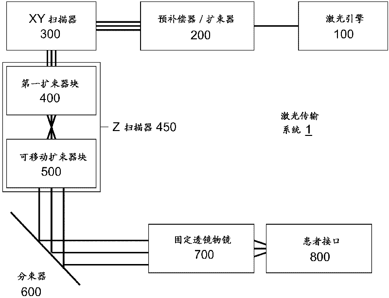
[0048] Some embodiments of the invention include systems for performing surgery in the lens of an eye using femtosecond laser pulses. Some integrated embodiments are also capable of performing both corneal and lens surgical procedures. Performing ophthalmic surgery in the lens of the eye is associated with qualitatively different requirements than corneal surgical procedures.

[0049] The main differences between currently described lens surgery laser systems and corneal systems include:

[0050] 1. Femtosecond laser pulses will be reliably generated. High repetition rate femtosecond pulses allow the use of less energy per pulse, which provides greater control and precision to the operator of the system. However, reliably generating femtosecond pulses is quite a challenge compared to the nanosecond or picosecond pulses used in some existing systems.

[0051] 2. The surgical laser beam is significantly refracted as it propagates through a maximum of 5 mm of refractive media ...


PUM


Abstract

A laser system for ophthalmic surgery includes a laser source to produce a surgical pulsed laser beam, an XY scanner to scan the surgical pulsed laser beam in XY transverse directions, a Z scanner, to scan the XY scanned laser beam along a Z axis, an objective, to focus the XYZ scanned beam into a focal spot in a target region, and a computational controller, to use a computational process to control at least one of the Z scanner and the XY scanner, to control an optical distortion of the focused scanned beam.

Description

[0001] Cross References to Related Applications [0002] This application claims the benefit of and priority to Utility Model Application Serial No. 12 / 511,961, "Optical System for Ophthalmic Surgical Laser," filed July 29, 2009, which application is hereby incorporated by reference in its entirety. technical field [0003] The present invention relates to systems for surgery on the anterior segment of the eye using femtosecond lasers, and more particularly to embodiments that minimize optical distortion of the laser beam while scanning and focusing the laser beam into the eye. Background technique [0004] The present application describes examples and embodiments of techniques and systems for laser surgery of the lens within the anterior segment of the eye by photodisruption caused by laser pulses. The various lens surgery procedures used to remove the lens utilize various techniques to break the lens into small pieces that can be removed from the eye through small incisio...

Claims


Application Information

Patent Timeline
IPC IPC(8): A61F9/008A61N5/067G02B26/08G02F1/29
CPCA61F2009/00848G02B27/0075A61F2009/00897A61F2009/00859A61F2009/0087A61F9/00825A61F9/008G02B27/0025A61F2009/00872
Inventor F・拉克希J・巴克
Owner ALCON INC
Why Eureka
Try Eureka