
Double-station CNC (computer numerical control) vertical ball cage arc raceway groove and ball hole grinding machine

A CNC vertical, double-station technology, applied in the direction of grinding machines, grinding machine parts, manufacturing tools, etc., can solve the problems of increasing the tolerance of ball holes and grooves of the ball cage, wasting processing time, etc., to improve the contact strength and The effect of transmission accuracy, improved assembly accuracy and convenient operation

Inactive Publication Date: 2012-07-25
ANHUI LICHENG MACHINERY EQUIP
View PDF6 Cites 13 Cited by
  • Summary
  • Abstract
  • Description
  • Claims
  • Application Information

AI Technical Summary

Problems solved by technology

[0004] However, this kind of machine tool can only process the ball cage groove, and the ball cage actually needs to process the ball hole of the ball cage. The ball hole of the ball cage and the groove have extremely high shape and position tolerance requirements, which requires the workpiece to grind the groove. , then disassemble and re-clamp, and use another ball hole special grinder for ball hole grinding. This secondary clamping processing method virtually increases the tolerance of the ball cage ball hole and channel, and also wastes processing time.

Method used


Image

  • Double-station CNC (computer numerical control) vertical ball cage arc raceway groove and ball hole grinding machine
  • Double-station CNC (computer numerical control) vertical ball cage arc raceway groove and ball hole grinding machine

Examples


Embodiment Construction

[0014] In order to make the technical means, creative features, goals and effects achieved by the present invention easy to understand, the present invention will be further described below in conjunction with specific illustrations.

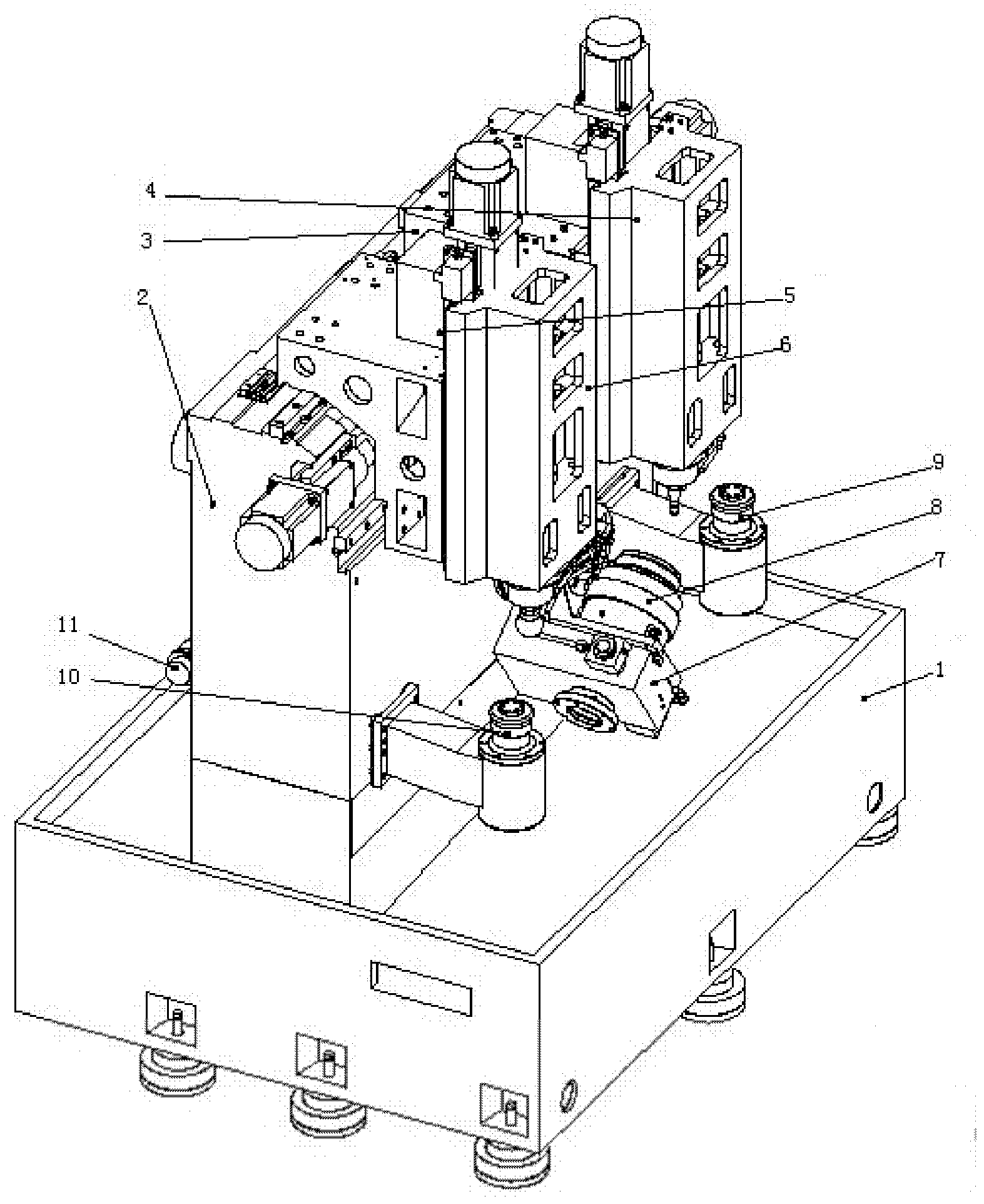
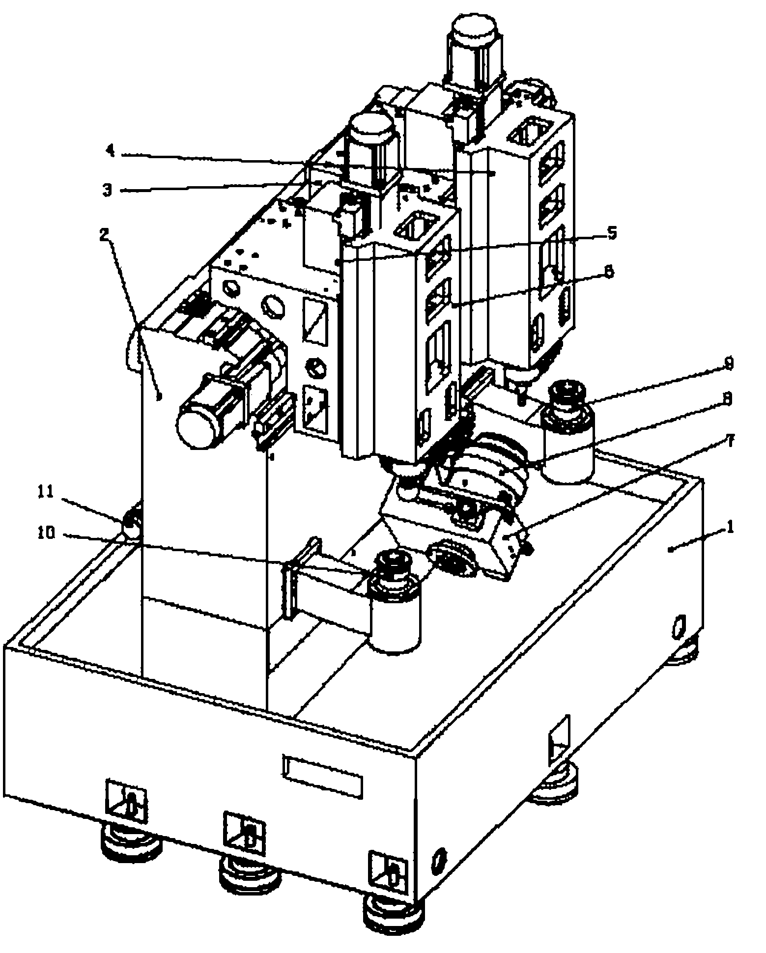
[0015] Such as figure 1 As shown, the CNC vertical double-station spherical cage arc groove ball hole grinder includes a basket-shaped bed 1, a basket-shaped column 2 is fixedly installed on the rear side of the basket-shaped bed 1, and the first sliding saddle 3 and The basket-shaped columns 2 are slidably connected along the left and right direction with the slide rail as the guide; On the headstock 4; the second sliding saddle 5 and the basket-shaped column 2 are slidably connected in the left and right direction with the slide rail as the guide, and the second headstock 6 and the second slide saddle 5 are slid in the vertical direction with the slide rail as the guide connection, the ball hole grinding wheel is fixed on the second headstock...


PUM


Abstract

The invention discloses a double-station CNC (computer numerical control) vertical ball cage arc raceway groove and ball hole grinding machine. The grinding machine is characterized in that a cage-shaped column is installed on the rear part of the upper surface of a cage-shaped machine body; a first sliding saddle and a second sliding saddle are installed on the cage-shaped column in parallel and can slide left and right along the cage-shaped column; a first main shaft box is fixed on the first sliding saddle and can slide up and down along the sliding saddle; a raceway groove grinding wheel is fixed on the first main shaft box; a second main shaft box is fixed on the second sliding saddle and can slide up and down along the sliding saddle; a ball hole grinding wheel is fixed on the second main shaft box; a swing rotary table is installed on the upper surface of the cage-shaped machine body in the middle of the front side of the cage-shaped column; a positioning fixture is installed on the swing rotary table; and a swing transmission component of the swing rotary table is arranged at the rear of the cage-shaped column and drives the swing rotary table to rotate in an indexing manner. The double-station CNC vertical ball grinding machine is formed by integrating the CNC vertical ball cage arc raceway groove grinding machine, the ball cage ball hole grinding machine and the swing rotary table carrying out swing motion. The grinding machine has a reasonable structure and is convenient to operate.

Description

technical field [0001] The invention relates to the technical field of grinding machines, in particular to a double-station numerical control vertical grinding machine for grinding arc groove ball holes of ball cages. Background technique [0002] Ball cage universal joints are commonly used in the front front drive of cars and other mechanical transmissions with high requirements. The ball cage universal joint mainly consists of a star-shaped sleeve of the outer fairway, a steel ball, a cage and a bell-shaped shell with an inner fairway. The number of steel balls is generally six, and the corresponding star-shaped sleeve and bell-shaped shell have six fairways. Theoretically, the steel ball can be in line contact with the ballway in the bell-shaped shell, but due to manufacturing and installation errors, the actual situation is generally point contact, and the contact positions of these points are not necessarily ideal. [0003] In order to improve the contact condition, ...

Claims


Application Information

Patent Timeline
IPC IPC(8): B24B25/00B24B41/06B24B53/06
CPCB23Q39/00
Inventor 周庆成金平
Owner ANHUI LICHENG MACHINERY EQUIP
Learn More