Blast furnace blowing rotary-wheel dehumidification method

A technology of dehumidification with a rotary wheel and blast furnace blast, which is applied in the field of ironmaking blast furnaces, can solve problems such as high operating costs, larger floor space, and increased investment costs, so as to save operating costs, reduce ironmaking coke ratio, and save recycle The effect of thermal energy consumption

Inactive Publication Date: 2012-07-25
WISDRI ENG & RES INC LTD
View PDF4 Cites 11 Cited by
  • Summary
  • Abstract
  • Description
  • Claims
  • Application Information

AI Technical Summary

Problems solved by technology

The surface cooling and freezing dehumidification method is that after the air is supercooled and dehumidified by the surface cooler, it is heated in the hot blast stove and then sent to the blast furnace, which causes energy waste and high operating costs.
Lithium bromide refrigeration units need to be equipped with cooling water pumps, cooling water pumps, cooling towers and other equipment, design complex cooling water and cooling water system pipelines, and arrange special refrigeration stations, so the floor space becomes larger and investment costs increase
The lithium bromide refrigeration unit is mainly composed of generators, absorbers, evaporators, condensers, solvent pumps, and solution pumps. There are many moving parts, which will generate large noise during operation, which is not conducive to the working environment of workers.
[0005] In addition, the freezing dehumidification method is suitable for occasions where the air dew point temperature is higher than 4°C, and it is not suitable for low-temperature air below 4°C.
At the same time, it is necessary to drain water after freezing and dewatering, and to demist the dehumidified air. If the drainage is not timely, it will affect the safe operation of the fan.

Method used


Image

  • Blast furnace blowing rotary-wheel dehumidification method
  • Blast furnace blowing rotary-wheel dehumidification method

Examples


Embodiment Construction

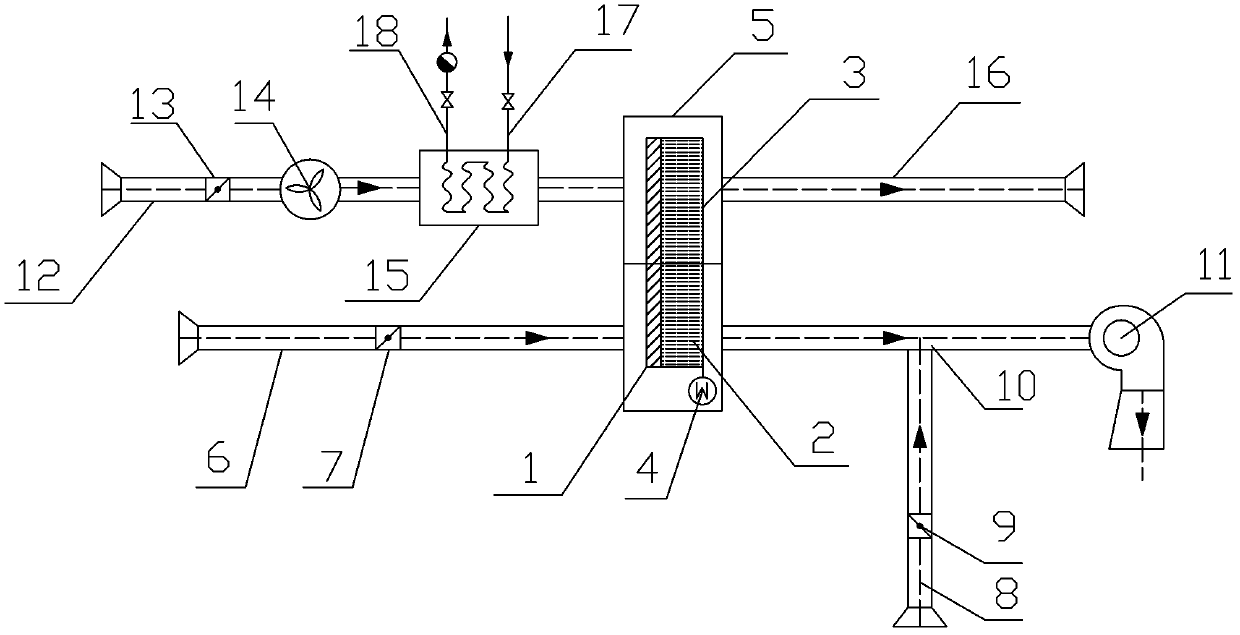
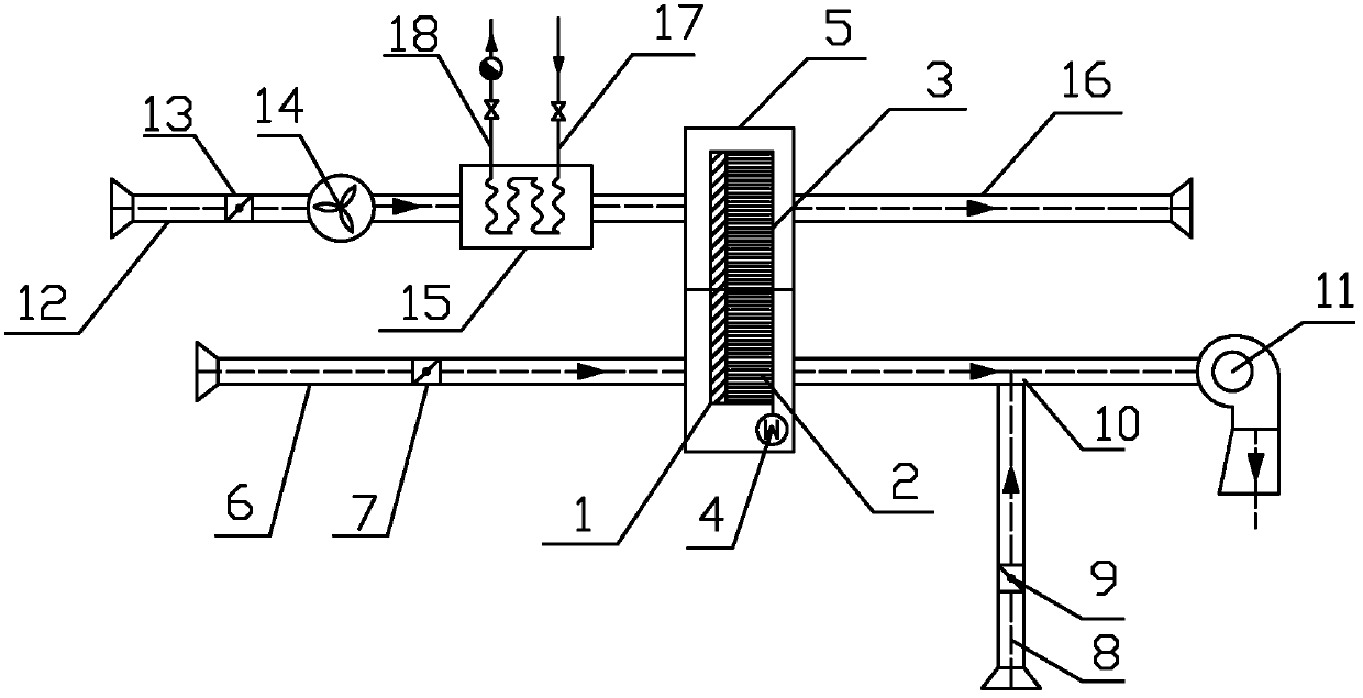
[0027] The following is attached figure 1 and Examples further illustrate the present invention, but do not limit the present invention.

[0028] The blast furnace blast runner dehumidification method of the present invention uses the runner to dehumidify low-temperature and low-humidity air, and mainly includes a blast runner dehumidification link and a runner regeneration link, and also includes a bypass link and a heat source steam link. In the dehumidification process of the rotary dehumidifier, one side of the shell 5 of the rotary dehumidifier is connected to the inlet air pipe 6, and the inlet air valve 7 is installed on the inlet air pipe 6, and the shell 5 of the rotary dehumidifier is equipped with a filter 1, a dehumidification wheel 2 and a rotary Wheel motor 4, the other side of the wheel dehumidifier housing 5 is connected to the outlet air duct 10, and the outlet air duct 10 is connected to the blower 11; Connected, the regenerated air inlet air pipe 12 is equi...


PUM


Abstract

The invention relates to a blast furnace blowing rotary-wheel dehumidification method, which mainly comprises a rotary wheel dehumidifier which is provided with a rotary wheel dehumidification zone and a rotary wheel regeneration zone and can perform circulating dehumidification and then regeneration. An inlet air pipe and an outlet air pipe are respectively arranged on two sides of the rotary wheel dehumidification zone; a regeneration air inlet air pipe and a regeneration air outlet air pipe are respectively arranged on two sides of the rotary wheel regeneration zone; an inlet air valve is arranged on the inlet air pipe; and the outlet air pipe is connected with a blast blower. The method is characterized in that a heater, a ventilator and a regeneration air valve are sequentially arranged on the regeneration air inlet air pipe; and a heater steam supply pipe and a heater condensation drain pipe are respectively communicated with the heater. After dehumidification is finished by using the method, the air temperature increases by a certain range, the process that air is supercooled firstly and then heated for dehumidification of a surface cooler is avoided, and the reheating energy consumption is saved. The method has the advantages that the efficiency is high, steam is used as a heat source, and the steam resource from metallurgical plants is sufficiently utilized.

Description

technical field [0001] The invention relates to a dehumidification method for blast furnace ironmaking blast runners, belonging to the technical field of ironmaking blast furnaces. Background technique [0002] The ironmaking process is an important part of energy saving in my country's iron and steel industry. The coke ratio of key iron and steel enterprises is lower than 390kg / tFe, but some small and medium iron and steel enterprises have higher coke ratio, some even reach 488kg / tFe, and the fuel ratio is 560kg / tFe about. [0003] Blast furnace blast dehumidification is an important measure for energy saving and consumption reduction of blast furnaces. Through blast dehumidification, blast furnace output can be increased, coal injection ratio can be increased and coke ratio can be reduced. For every 1g / m3 decrease in the moisture content of the blast furnace blast, the comprehensive coke ratio will decrease by 0.7kg / tFe, which is equivalent to 0.68kgce / tFe; Every time the...

Claims


Application Information

Patent Timeline
Patent Type & Authority Applications(China)
IPC IPC(8): C21B9/16B01D53/26B01D53/04
CPCY02P10/20
Inventor 胡建亮盖东兴黄永红
Owner WISDRI ENG & RES INC LTD
Why Eureka
Try Eureka