Electroplating system and electroplating method

An electroplating bath and electroplating solution technology, applied in electrical components, electrolytic process, electrolytic components, etc., can solve the problems of low current density, affecting electroplating quality, and high current density, and achieve improved uniformity, improved electroplating quality, and uniform density distribution. Effect

Inactive Publication Date: 2012-07-25
AVARY HLDG (SHENZHEN) CO LTD +1
View PDF6 Cites 11 Cited by
  • Summary
  • Abstract
  • Description
  • Claims
  • Application Information

AI Technical Summary

Problems solved by technology

However, since the current of the circuit board is introduced through the conductive pinch of the hanger, the current density of the two edge areas of the circuit board to be plated close to the conductive pinch is relatively high, while the current density of the central area of ​​the circuit board far away from the conductive pinch is relatively high. lower current density
Moreover, since the deposition amount of metal ions is proportional to the current density, the metal deposited on the two edge areas connected to the circuit board and the conductive pinch is relatively thick, while the metal deposited on the central area of ​​the circuit board is relatively thin, resulting in the unevenness of metal deposition. Uneven thickness affects the quality of electroplating

Method used


Image

  • Electroplating system and electroplating method
  • Electroplating system and electroplating method
  • Electroplating system and electroplating method

Examples


Embodiment Construction

[0054] The electroplating system and electroplating method of the technical solution will be further described in detail below in conjunction with the accompanying drawings and embodiments.

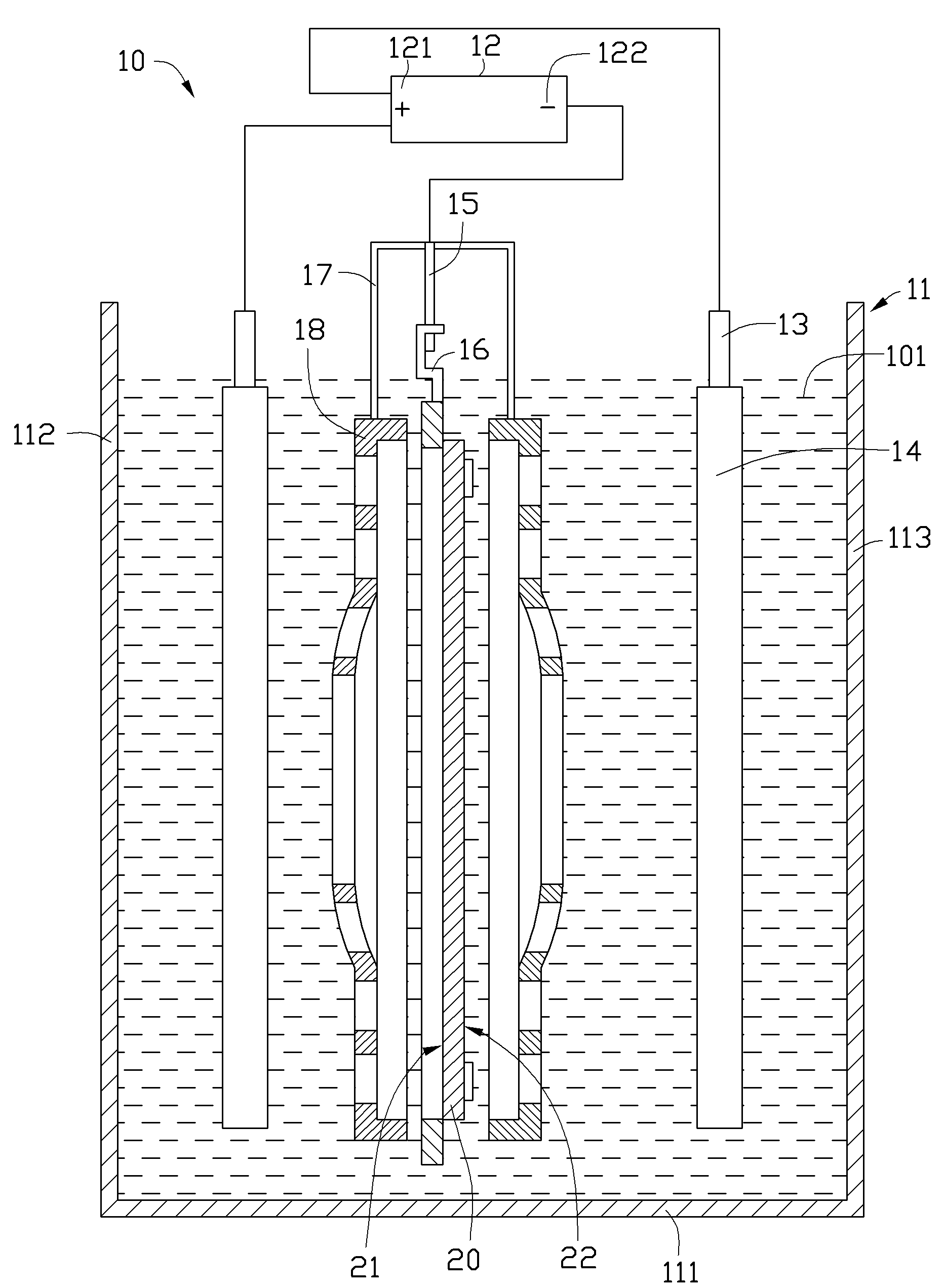
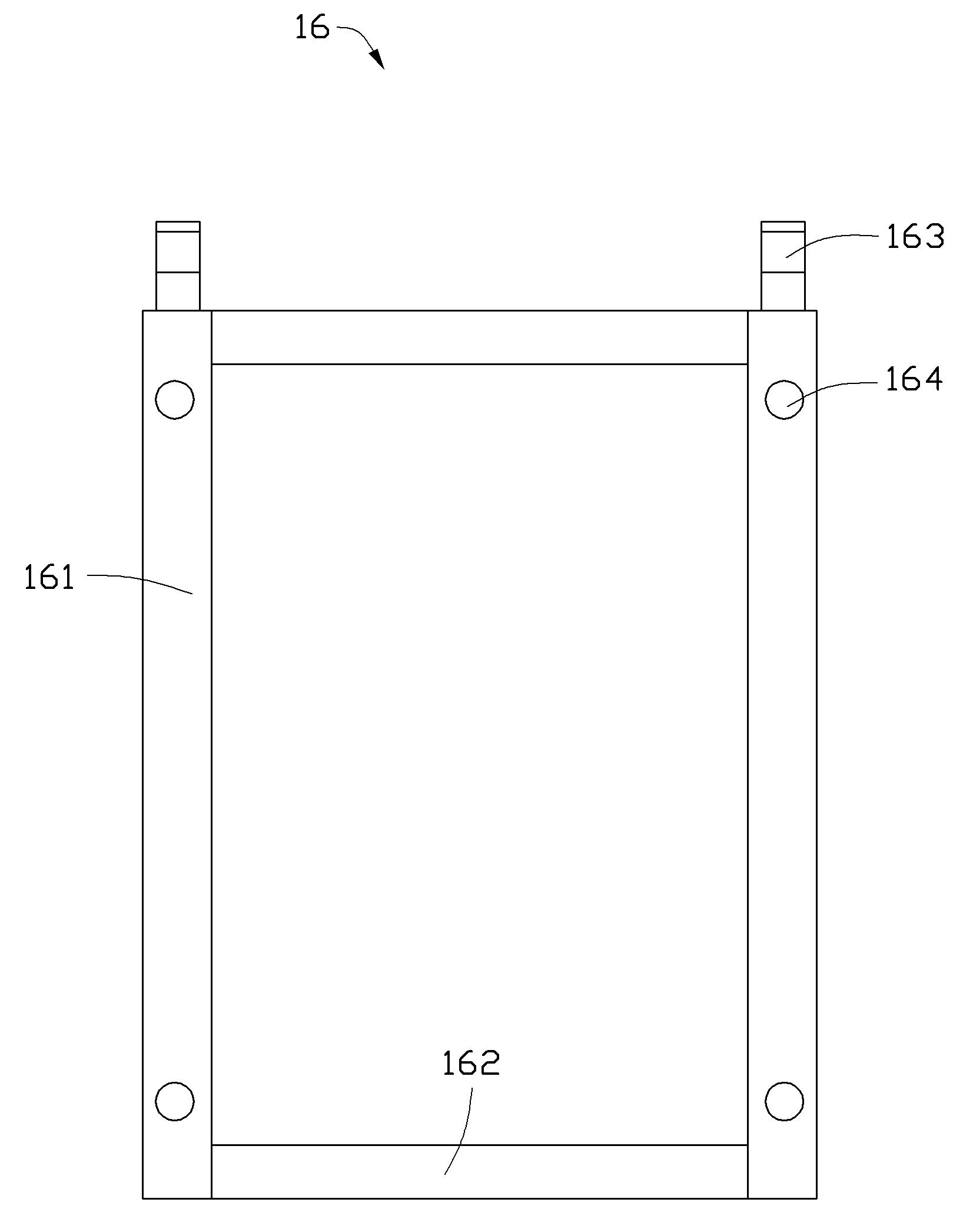
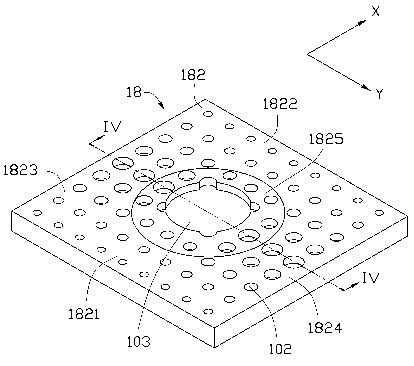
[0055] see Figure 1 to Figure 2 , The first embodiment of the technical solution provides an electroplating system 10 for electroplating at least one circuit board 20 . The electroplating system 10 includes an electroplating tank 11 , a power supply device 12 , an anode rod 13 , an electroplating anode 14 , a cathode rod 15 , a hanger 16 , an auxiliary cathode rod 17 and an auxiliary cathode cover 18 . The electroplating anode 14 , hanger 16 and auxiliary cathode cover 18 are all arranged in the electroplating tank 11 . The auxiliary cathode cover 18 is located between the electroplating anode 14 and the hanger 16 .

[0056] Specifically, the electroplating tank 11 has a bottom wall 111 , a first side wall 112 and a second side wall 113 . The first sidewall 112 and the second sidewall...


PUM

PropertyMeasurementUnit
lengthaaaaaaaaaa
lengthaaaaaaaaaa

Abstract

The invention discloses an electroplating system which comprises an electroplating bath, a power supply device, an anode bar, an electroplating anode, a cathode bar, a hanging rack, an auxiliary cathode bar and an auxiliary cathode shield, wherein the anode bar, the cathode bar and the auxiliary cathode bar are connected to the power supply device; the electroplating anode is fixed on the anode bar; the hanging rack is fixed on the cathode bar, and provided with a plurality of conductive pinch points for fixing a circuit board; the auxiliary cathode shield is fixed on the auxiliary cathode bar, opposite to the hanging rack, and arranged between the hanging rack and the electroplating anode; the auxiliary cathode shield comprises a shield body which is dead against the circuit board; the shield body comprises a peripheral area and a central area; the plurality of conductive pinch points are opposite to the peripheral area; the peripheral area is provided with a first through hole, and the central area is provided with a second through hole; and the first and second through holes are used for controlling the density distribution of metal ions precipitated from the electroplating anode after passing through the auxiliary cathode shield. The invention also provides an electroplating method using the electroplating system above.

Description

technical field [0001] The invention relates to electroplating technology, in particular to an electroplating system and an electroplating method. Background technique [0002] With the rapid development of the electronic industry, the manufacturing technology of circuit boards, which are the basic components of electronic products, is becoming more and more important. Circuit boards are generally made of copper-clad substrates through a series of processes such as cutting, drilling, electroplating, exposure, development, etching, lamination, printing, and molding. For details, please refer to the article "Dielectric characterization of printed circuit board substrates" published by C.H.Steer et al. in Proceedings of the IEEE, Vol.39, No.2 (August 2002). [0003] Among them, electroplating is an important manufacturing process of circuit board production, which mainly uses electroplating system to selectively plate copper on the surface of the circuit board and plate copper...

Claims


Application Information

Patent Timeline
Patent Type & Authority Applications(China)
IPC IPC(8): C25D7/00C25D17/00C25D19/00H05K3/18
CPCC25D17/008C25D17/06
Inventor 郑建邦
Owner AVARY HLDG (SHENZHEN) CO LTD
Why Eureka
Try Eureka