Gear-rack drill string heave compensator for floating drilling platform

A technology of rack and pinion and drilling platform, applied in the direction of drilling equipment, drill pipe, drill pipe, etc., can solve the problems of lagging, multi-energy, low compensation accuracy, etc., to achieve enhanced adaptability and reliability, sensitive compensation response, compensation good effect

Inactive Publication Date: 2012-07-25
SOUTHWEST PETROLEUM UNIV
View PDF8 Cites 15 Cited by
  • Summary
  • Abstract
  • Description
  • Claims
  • Application Information

AI Technical Summary

Problems solved by technology

However, it is difficult to effectively suppress the impact of ultra-low frequency and broadband random vibration waves, currents, and tides, and the compensation accuracy is not high, so the compensation effect of the passive compensation system is not ideal, and there is a certain hysteresis phenomeno

Method used


Image

  • Gear-rack drill string heave compensator for floating drilling platform
  • Gear-rack drill string heave compensator for floating drilling platform
  • Gear-rack drill string heave compensator for floating drilling platform

Examples


Embodiment 1

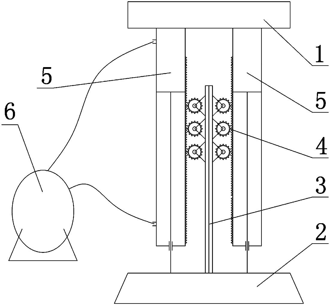
[0023] Such as figure 1 As shown, a rack-and-pinion drilling string heave compensation device for a floating drilling platform is installed on the derrick and crown block platform of a conventional floating drilling platform. It includes traveling block 1, hook 2, and a piston-type hydraulic cylinder 5. Gas storage / liquid tank 6, rigid rod 3 and rack and pinion mechanism 4, hydraulic cylinder 5 is fixedly connected to traveling carriage 1, the piston rod of hydraulic cylinder 5 is fixed on hook 2, and the upper and lower ends of hydraulic cylinder 5 are respectively Connected with the gas / liquid tank 6, the rigid rod 3 is arranged on the hook 2, the rigid rod 3 is connected with the hydraulic cylinder 5 through the rack and pinion mechanism 4, and the gear shaft of the gear in the rack and pinion mechanism 4 A variable frequency motor is connected.

[0024] The rigid rod 3 is arranged in the middle of the hook 2 between the two piston rods and parallel to the piston rods, the...

Embodiment 2

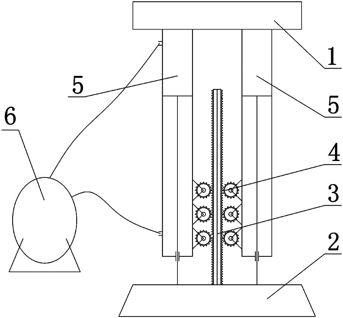
[0028] Such as figure 2 As shown, a rack-and-pinion drilling string heave compensation device for a floating drilling platform is installed on the derrick and crown block platform of a conventional floating drilling platform. It includes traveling block 1, hook 2, and a piston-type hydraulic cylinder 5. Gas storage / liquid tank 6, rigid rod 3 and rack and pinion mechanism 4, hydraulic cylinder 5 is fixedly connected to traveling carriage 1, the piston rod of hydraulic cylinder 5 is fixed on hook 2, and the upper and lower ends of hydraulic cylinder 5 are respectively Connected with the gas / liquid tank 6, the rigid rod 3 is arranged on the hook 2, the rigid rod 3 is connected with the hydraulic cylinder 5 through the rack and pinion mechanism 4, and the gear shaft of the gear in the rack and pinion mechanism 4 A variable frequency motor is connected.

[0029] The rigid rod 3 is arranged in the middle of the hook 2 between the two piston rods and parallel to the piston rods, th...


PUM


Abstract

The invention discloses a gear-rack drill string heave compensator for a floating drilling platform, which comprises a traveling block (1), a large hook (2), a gear-rack mechanism (4), a rigid rod (3) and a compensating cylinder system. The compensating cylinder system comprises a piston-type hydraulic cylinder (5) and a gas/liquid storage tank (6), the hydraulic cylinder (5) is fixedly connected onto the traveling block (1), the large hook (2) is fixedly connected with a piston rod of the hydraulic cylinder (5), the rigid rod (3) is arranged on the large hook (2) and connected with the hydraulic cylinder (5) through the gear-rack mechanism (4), and a gear shaft for a gear in the gear-rack mechanism (4) is connected with a variable frequency motor. The gear-rack drill string heave compensator has the advantages that a driving compensating system and a driven compensating system are adopted to simultaneously achieve response sensitivity, rapidness and precision of compensation of the driving system and low energy consumption and the like of the driven system, the compensator is simple in structure and fine in compensating effect, and adaptability and reliability of the compensator are enhanced.

Description

technical field [0001] The invention relates to the technical field of heave compensation devices for marine floating platforms, in particular to a rack and pinion drill string heave compensation device for floating drilling platforms. Background technique [0002] With the depletion of land resources, the strategic vision of the world's economic development is focused on the ocean, and the development of marine technology and high-tech equipment is particularly important. In the field of petroleum, with the development of China's economy, especially the rapid development of the petrochemical and automobile industries as the pillar industries, the contradiction of insufficient supply of oil and natural gas has become increasingly prominent. In view of the depletion of onshore oil resources, marching into the deep sea has become an inevitable trend. At present, the maximum working water depth of offshore oil drilling rigs has exceeded 3000m, and will continue to develop in a...

Claims


Application Information

Patent Timeline
IPC IPC(8): E21B19/09
Inventor 刘清友黎伟鲁柳利孙浩任涛
Owner SOUTHWEST PETROLEUM UNIV
Why Eureka
Try Eureka