Automatic positioning clamping mechanism for feeding and discharging materials in bell-shaped shell defect-detection/cleaning integrated machine

An automatic positioning and clamping mechanism technology, applied in the direction of chuck, manipulator, material magnetic variable, etc., can solve problems such as complex structure, unstable air pressure, and unsatisfactory results

Active Publication Date: 2012-07-25
SHEYANG HUATONG DETECTOR EQUIP
View PDF5 Cites 43 Cited by
  • Summary
  • Abstract
  • Description
  • Claims
  • Application Information

AI Technical Summary

Problems solved by technology

[0002] In the prior art, there are two kinds of positioning and clamping mechanisms in the loading and unloading of the all-in-one machine: the first one is to drive the double-sided tooth rack through the cylinder to drive the double-sector teeth to achieve the purpose of clamping. This method is not only complicated in structure, but also only suitable for One type of workpiece with a fixed size achieves accurate positioning. When the size of different types of workpieces changes, the center cannot be positioned because the jaws on the sector are in circular motion. The second type is that the two jaws are driven by double cylinders. Theoretically, the synchronization of the two jaws can be realized only by adjusting the pressure balance of the cylinders on both sides. Rarely used in actual production

Method used


Image

  • Automatic positioning clamping mechanism for feeding and discharging materials in bell-shaped shell defect-detection/cleaning integrated machine
  • Automatic positioning clamping mechanism for feeding and discharging materials in bell-shaped shell defect-detection/cleaning integrated machine
  • Automatic positioning clamping mechanism for feeding and discharging materials in bell-shaped shell defect-detection/cleaning integrated machine

Examples


Embodiment Construction

[0015] The present invention is described in detail below in conjunction with the accompanying drawings:

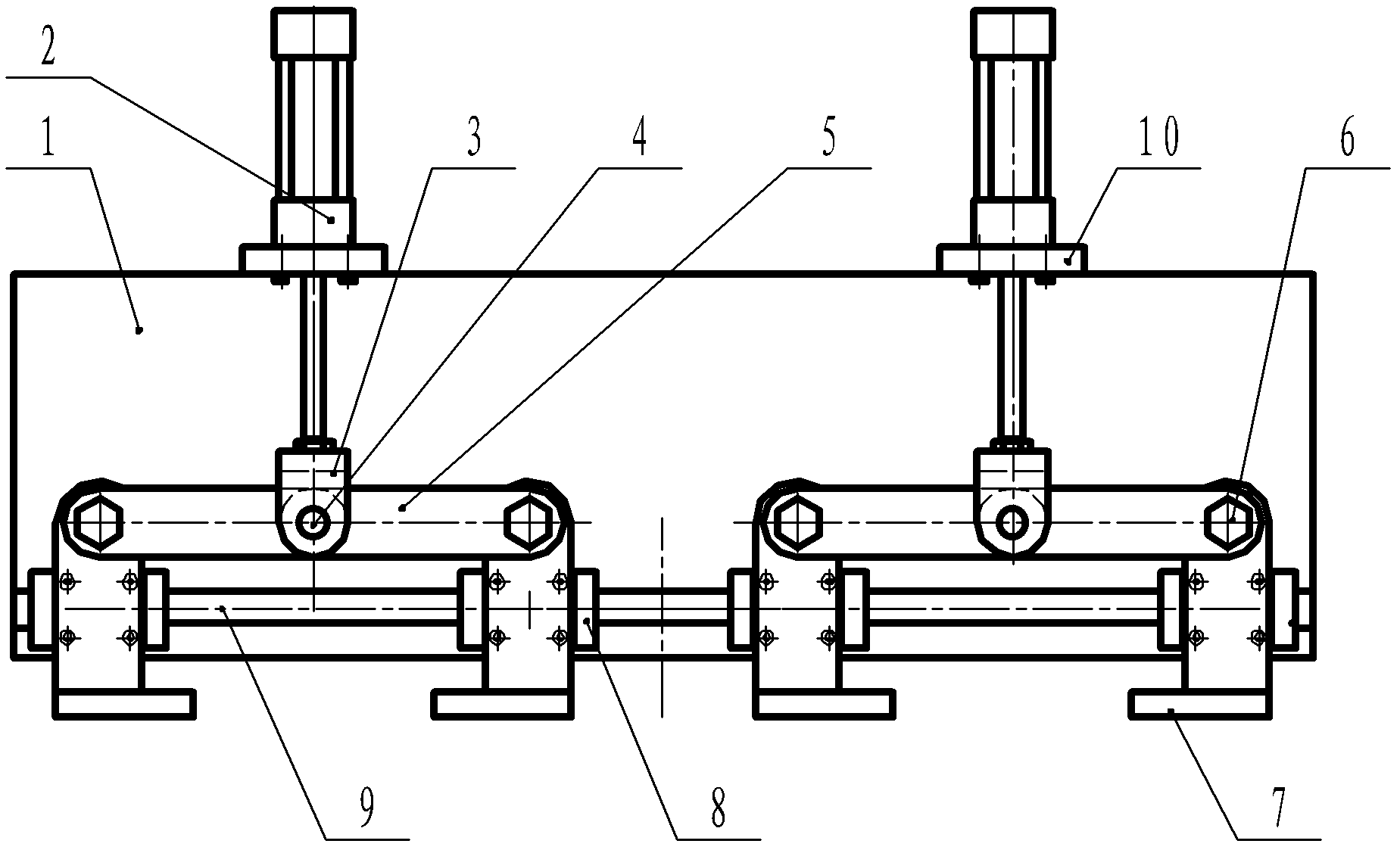
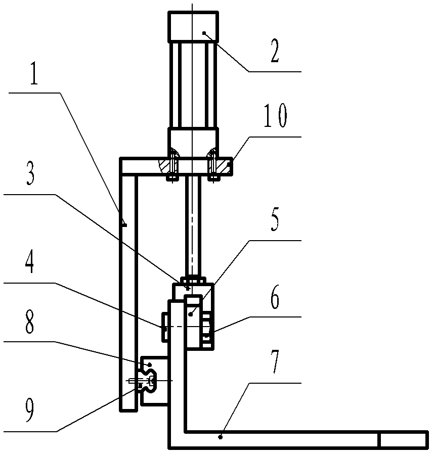
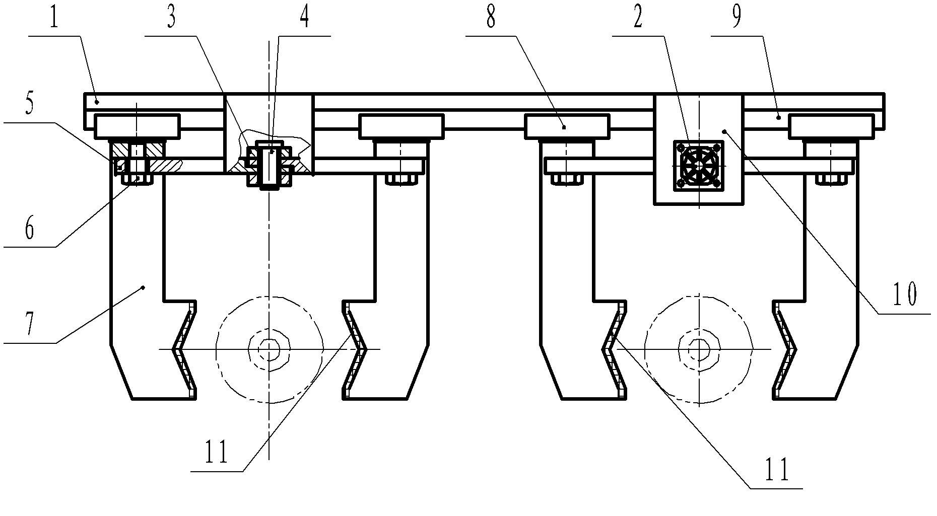
[0016] The invention includes an electrical control system in an integrated machine, a gas source supply device, and stations for feeding, pre-cleaning, magnetic particle inspection, demagnetization, cleaning, drying, and blanking. The left and right sides of the inspection station are respectively provided with There is an integrated chain conveying device, and the magnetic particle inspection station is equipped with a robot automatic loading and unloading device; the bell-shaped shell workpiece chain conveying device is transported from the loading station to the magnetic particle inspection station, and is automatically carried out by the robot. Longitudinal and lateral transfer to the magnetic particle inspection station. After the workpiece is inspected by the magnetic particle inspection station, it is moved to the subsequent demagnetization and cleaning conveyor li...


PUM


Abstract

The invention relates to an automatic positioning clamping mechanism used for feeding and discharging materials in a bell-shaped shell defect-detection / cleaning integrated machine. The mechanism is characterized by fixing a pair of cylinder connecting plates on the top surface of an installing substrate; two pairs of, in other words, four sliding blocks in all, are configured on a straight line guide track at the lower part in front of the installing substrate; a clamping jaw is L-shaped; V-shaped chucks are arranged on the internal side surface at the front parts of a pair of clamping jaw horizontal arms respectively; four clamping jaws are fixed on the four sliding blocks through a perpendicular arm respectively; a cylinder is fixed on the cylinder connecting plate; a movable joint is fixed on a stretching end of a piston rod of the cylinder; the movable joint is U-shaped and the opening thereof faces downwards; each pair of connecting rods are matched in a U-shaped slot of the movable joint rotationally through a hinge pin; and the other ends of each pair of connecting rods are matched on a pair of clamping jaw perpendicular arms rotationally through screws. According to the mechanism, working pieces of different models can be positioned and clamped accurately without adjustment; the adjusting working quantity of the machine can be reduced greatly; the operation is sensitive and reliable; and the production efficiency can be improved greatly.

Description

technical field [0001] The invention relates to a non-destructive testing machine, in particular to an automatic positioning and clamping mechanism in the loading and unloading of a bell-shaped shell magnetic particle flaw detection and cleaning integrated machine. Background technique [0002] In the prior art, there are two kinds of positioning and clamping mechanisms in the loading and unloading of the all-in-one machine: the first is to drive the double-sector teeth through the cylinder to push the double-sided rack to achieve the purpose of clamping. This method is not only complicated in structure, but also can only A workpiece with a fixed size can achieve accurate positioning. When the size of different types of workpieces changes, because the clamping jaws on the sector move in a circular motion, the center cannot be positioned; the second is that the two clamping jaws are driven by double cylinders. This method In theory, only by adjusting the pressure balance of t...

Claims


Application Information

Patent Timeline
Patent Type & Authority Applications(China)
IPC IPC(8): G01N27/84B08B13/00B25J15/08
Inventor 刘宁兵吕道俊刘毅森
Owner SHEYANG HUATONG DETECTOR EQUIP
Why Eureka
Try Eureka