Driving device for pulse laser

A pulsed laser and driving device technology, applied to semiconductor laser excitation devices, excitation methods/devices, etc., can solve the problems of stripline driving waveform degradation, stripline inconvenience, length limitation, etc., and improve the quality of pulsed driving. , the effect of promoting technological progress and reducing difficulty requirements

Active Publication Date: 2013-04-24
SHANGHAI INST OF MICROSYSTEM & INFORMATION TECH CHINESE ACAD OF SCI
View PDF6 Cites 1 Cited by
  • Summary
  • Abstract
  • Description
  • Claims
  • Application Information

AI Technical Summary

Problems solved by technology

The length of the stripline is also strictly limited, generally within 30-50cm, if it is too long, the waveform will be significantly deteriorated
For practical applications, this kind of stripline is inconvenient because it cannot be bent at will, and the connectors are not easy to match. Installed in the optical path, but the drive module needs to be installed in a remote electric control cabinet, which brings great difficulties to the system arrangement
For unipolar lasers, since their impedance is generally higher than that of bipolar lasers, the stripline driving waveform is often degraded to the point where it cannot be used due to severe impedance mismatch in many cases, so it is necessary to customize a driving cable with special impedance according to the specific device
Since the impedance of the device may vary in a wide range, this kind of cable has poor versatility, poor interchangeability for different devices, high cost, inconvenient use, and its length needs to be limited

Method used


Image

  • Driving device for pulse laser
  • Driving device for pulse laser

Examples


Embodiment Construction

[0017] Below in conjunction with specific embodiment, further illustrate the present invention. It should be understood that these examples are only used to illustrate the present invention and are not intended to limit the scope of the present invention. In addition, it should be understood that after reading the teachings of the present invention, those skilled in the art can make various changes or modifications to the present invention, and these equivalent forms also fall within the scope defined by the appended claims of the present application.

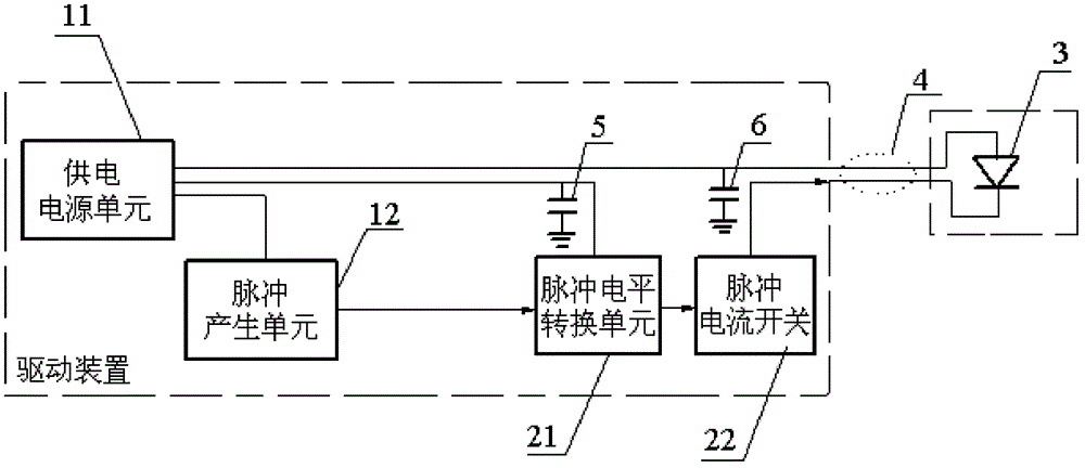
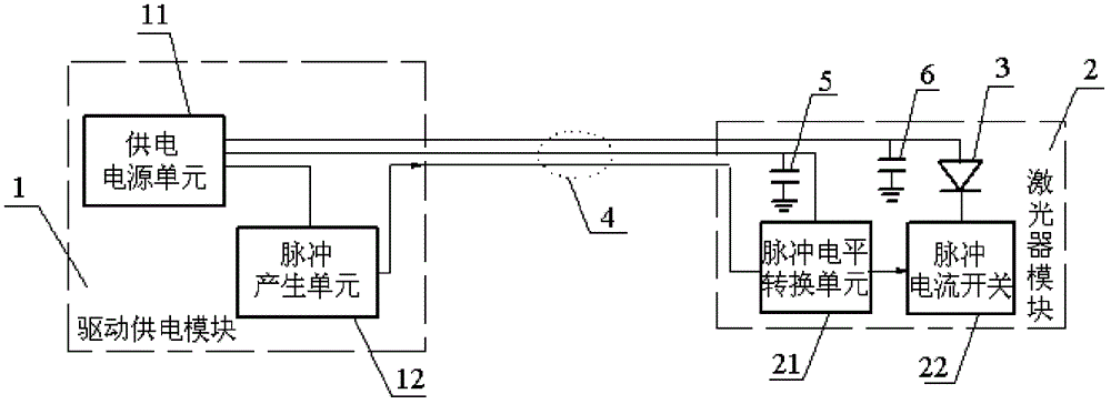
[0018] Such as figure 2 As shown, the present invention includes a drive power supply module 1 and a laser module 2, which are connected via a composite cable 4 composed of a common 50-ohm coaxial cable and common wires.

[0019] The driving power supply module 1 is only composed of a power supply unit 11 and a pulse generating unit 12 . The power supply unit 11 includes three groups of different voltages required by the sys...


PUM


Abstract

The invention relates to a driving device for a pulse laser. The driving device comprises a drive and power supply module and a laser module; the drive and power supply module comprises a power supply source unit and a pulse generating unit; the power supply source unit is used for supply power to the laser module and the pulse generating unit; the pulse generating unit is used for generating electrical pulses according to a required pulse parameter; the laser module comprises a pulse level conversion unit, a pulse current switch and the pulse laser; the pulse level conversion unit is used for stepping up the electrical pulses generated by the pulse generating unit to a required electrical level so as to meet the driving requirements of the pulse current switch; the pulse current switch is used for driving the pulse laser; the power supply source unit is respectively connected with the pulse level conversion unit and the pulse laser through power supply leads; and the pulse generatingunit is connected with the pulse level conversion unit through a coaxial cable. According to the driving device for the pulse laser, the short driving distance of the pulse laser can be prolonged, and the driving quality can be improved.

Description

technical field [0001] The invention relates to laser driving technology in the technical fields of optoelectronics, microelectronics and semiconductor lasers, in particular to a pulsed laser driving device. Background technique [0002] Pulsed semiconductor lasers have been widely used in many fields. In many application fields, laser pulses need to be as short as tens of nanoseconds to several nanoseconds, or even lower, such as lidar, laser ranging, laser gas detection, laser excitation and detection in physics research, etc. Such applications are different from traditional communication laser applications under high-speed continuous modulation. Under short-pulse working conditions, it is generally necessary to provide a large pulse driving current to the laser, and the transient power consumption is large, but because the duty cycle is generally small, the average power consumption is generally not large. For some special types of semiconductor lasers, such as quantum ...

Claims


Application Information

Patent Timeline
Patent Type & Authority Patents(China)
IPC IPC(8): H01S5/04
Inventor 张永刚顾溢
Owner SHANGHAI INST OF MICROSYSTEM & INFORMATION TECH CHINESE ACAD OF SCI
Why Eureka
Try Eureka