Piezoelectric wafer control type non-contact glue dispensing device

A piezoelectric chip and glue dispensing device technology, which is applied to the surface coating liquid device, embroidery machine mechanism, embroidery machine, etc., can solve the problems of poor consistency of glue points and slow glue dispensing speed, etc.

Inactive Publication Date: 2012-08-01
JILIN UNIV
View PDF5 Cites 25 Cited by
  • Summary
  • Abstract
  • Description
  • Claims
  • Application Information

AI Technical Summary

Problems solved by technology

[0009] The present invention proposes a piezoelectric chip-controlled non-contact dispensing device to solve the problems of poor glue dot consistency and slow dispensing speed of the contact dispensing dev

Method used


Image

  • Piezoelectric wafer control type non-contact glue dispensing device
  • Piezoelectric wafer control type non-contact glue dispensing device
  • Piezoelectric wafer control type non-contact glue dispensing device

Examples


Embodiment approach 1

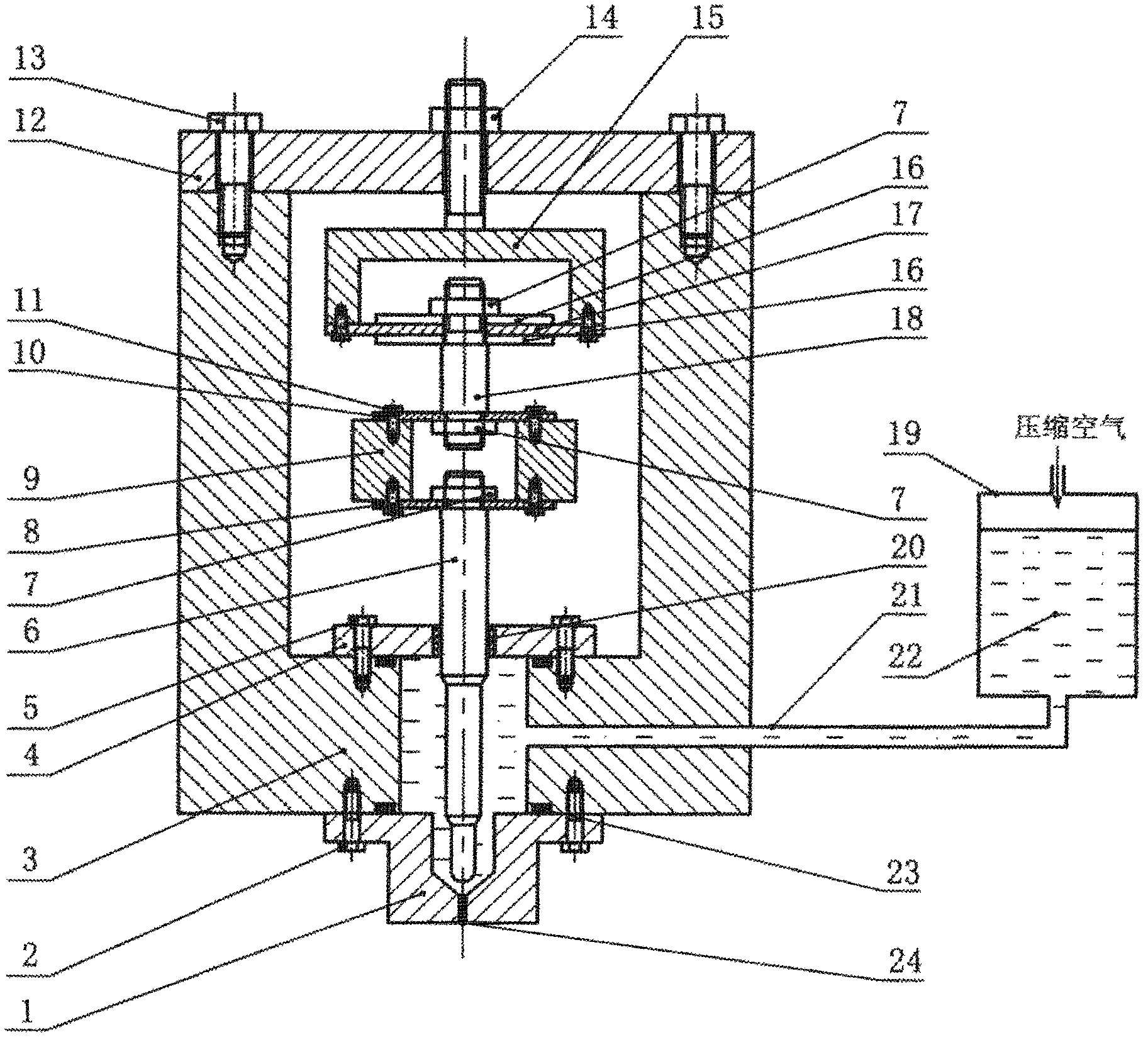
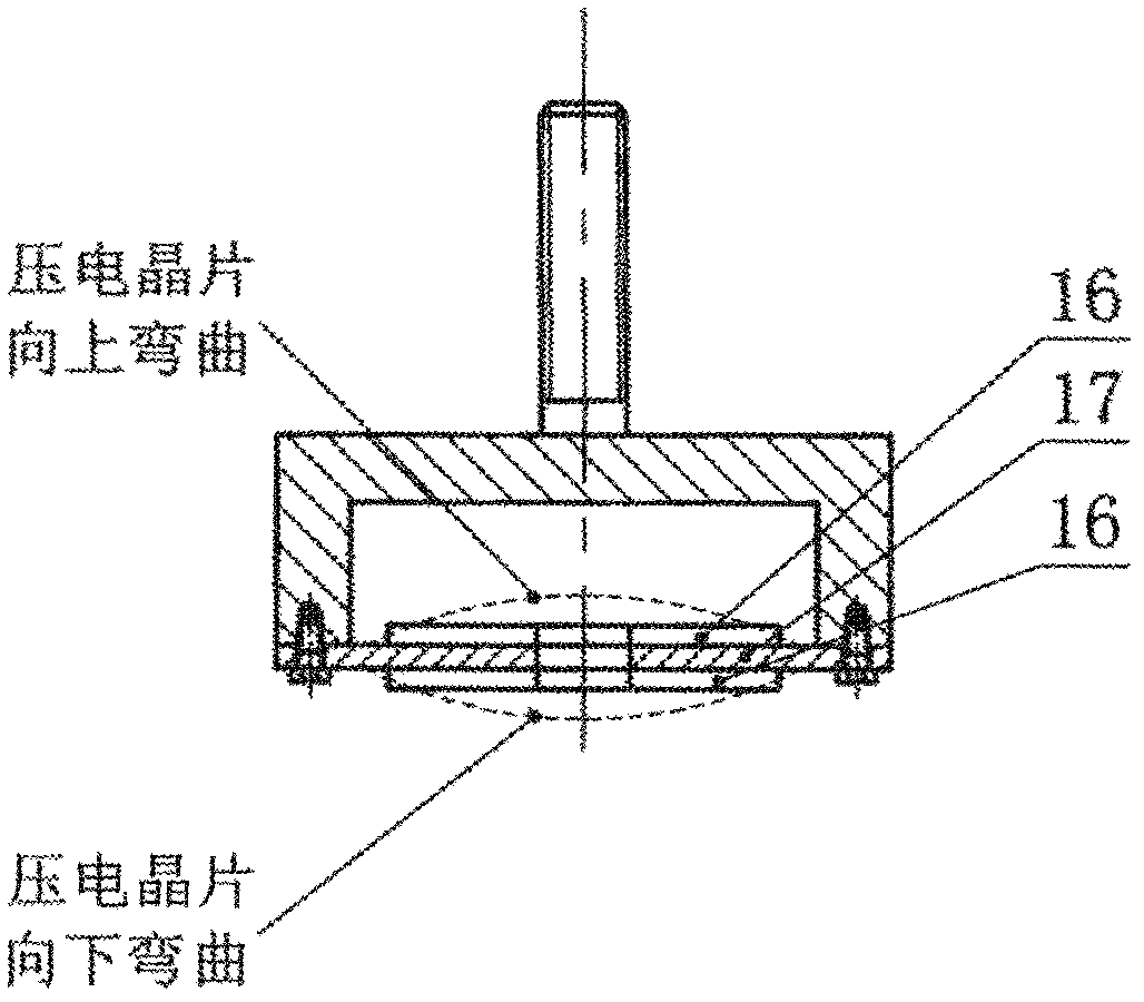
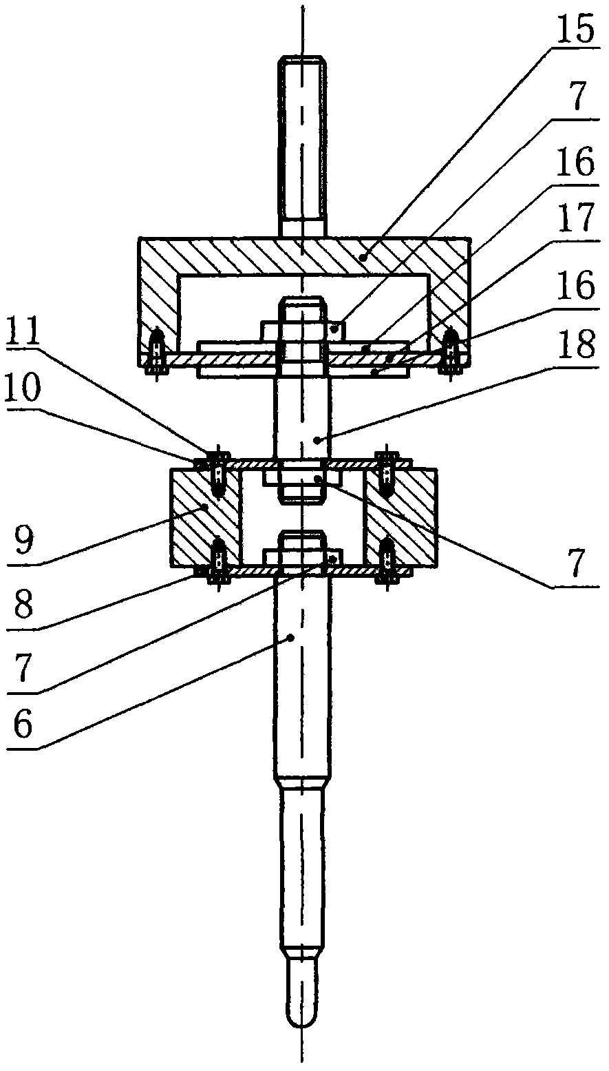
[0030] see figure 1As shown, a piezoelectric chip-controlled non-contact dispensing device of the present invention is composed of the piezoelectric chip displacement amplification mechanism and its auxiliary components shown in FIG. 3 . The piezoelectric chip displacement amplifying mechanism is made of piezoelectric chip (16), substrate (17), end cover (15), transmission vibration rod (18), set nut (7), diaphragm spring 1 (10), mass block ( 9), diaphragm spring II (8), striker (6) form. The piezoelectric wafer (16) is bonded to the base plate (17), and the base plate (17) is fixedly connected to the end cover (15); the two ends of the vibration transmission rod (18) are respectively connected to the piezoelectric wafer (16) and the diaphragm spring 1 ( 10) Fixed connection; the diaphragm spring I (10) is fixedly connected to the mass block (9); the striker (6) is connected to the diaphragm spring II (8), and the diaphragm spring II (8) is fixed to the mass block (9). The n...

Embodiment approach 2

[0036] see Figure 4 As shown, the piezoelectric wafer (16), substrate (17), vibration transmission rod (18), diaphragm spring II (10), mass block (9), diaphragm spring I (8) and connecting rod (31) are composed of The displacement amplifying mechanism amplifies the tiny displacement of the piezoelectric chip, and the connecting rod (31) is connected with the flexible hinge (32). One end of the flexible hinge (32) is fixed on the cavity (3), and the other end is fixedly connected with the striker (6). Through the lever amplification of the flexible hinge (32), when the displacement amplification mechanism moves downward, the striker (6) The displacement is further amplified, which can drive the more viscous glue to realize automatic distribution and realize the injection of glue.

Embodiment approach 3

[0038] see Figure 5 As shown, the piezoelectric wafer (16), substrate (17), vibration transmission rod (18), diaphragm spring II (10), mass block (9), diaphragm spring I (8) and connecting rod (33) are composed of The displacement amplifying mechanism of the horizontal placement, connecting rod (33) is fixedly connected with conversion lever (34), and the middle part of conversion lever (34) is hinged on the cavity (3), and at the other end, conversion lever (34) and striker ( 6) Fixed connection. The micro-displacement of the piezoelectric chip (16) is amplified by the displacement amplifying mechanism, and then through the conversion lever (34), the displacement in the horizontal direction is converted into the displacement in the vertical direction of the striker (6), thereby driving the automatic distribution of the glue liquid and realizing the glue liquid injection.


PUM


Abstract

The invention provides a novel piezoelectric wafer control type non-contact glue dispensing device with the advantages that the structure is simple, the maintenance is convenient, and the cost is low. The micro vibration displacement of a piezoelectric wafer is amplified through a displacement amplification mechanism, a firing pin is driven to vertically move, and the glue liquid spraying is realized. The novel piezoelectric wafer control type non-contact glue dispensing device adopts the following technical scheme that the displacement amplification mechanism consists of the piezoelectric wafer, a diaphragm spring, a mass block, a vibration rod and the firing pin, when the voltage frequency exerted on the piezoelectric wafer approaches to or is identical to the inherent frequency of the displacement amplification mechanism, the displacement amplification mechanism reaches the resonance state, the output displacement and the speed of the firing pin reach the maximum values, the glue liquid is driven to be sprayed out from a spray nozzle, and the automatic distribution of the glue liquid is realized. The novel piezoelectric wafer control type non-contact glue dispensing device can be used for the fields of precise chemicals, medicine quantitative distribution, biomedicine and the like, is particularly applied to the technical field of high-viscosity glue dispensing in semiconductor encapsulation and is used for the chip fixation, the surface mounting and the bottom filling in the electronic encapsulation, the fluorescent powder coating in a liquid crystal display flat plate and the like.

Description

technical field [0001] The invention relates to a piezoelectric wafer-controlled non-contact dispensing device, which belongs to the field of microelectronic packaging. Background technique [0002] Fluid dispensing technology is a key technology in microelectronic packaging. It can be structured to form points, lines, surfaces (coating) and various graphics, and is widely used in chip fixing, package flipping and chip coating. This technology precisely dispenses fluids in a controlled manner, transferring ideally sized fluids (flux, conductive glue, epoxies, adhesives, etc.) To realize the mechanical or electrical connection between components, this technology requires the dispensing system to have good operating performance, high dispensing speed, good consistency and high precision of the dispensing glue points. [0003] The traditional dispensing technology is contact dispensing, including metering tube dispensing, piston dispensing and time / pressure dispensing. This k...

Claims


Application Information

Patent Timeline
IPC IPC(8): B05C5/02D05C11/10
CPCB05C5/0225
Inventor 焦晓阳刘建芳丁宁宁江海谷峰春
Owner JILIN UNIV
Why Eureka
Try Eureka