Spatial wedge type double-clutch

A dual clutch and clutch technology, applied in clutches, one-way clutches, mechanical equipment, etc., can solve the problems of low reliability, high cost, and complicated manufacturing process

Active Publication Date: 2012-08-01
路亚科消防车辆制造有限公司
View PDF13 Cites 6 Cited by
  • Summary
  • Abstract
  • Description
  • Claims
  • Application Information

AI Technical Summary

Problems solved by technology

This not only makes the dual-clutch system too complex, too many components, too large in volume and mass, complicated in manufacturing process and high in cost, and low in reliability, but also makes it necessary to engage and consume too much energy.
At the same time, the dual-clutch system is not easy to be miniaturized and lightweight, and it is not easy to realize wire-controlled transmission and remote control, and the action response is not high enough.
[0005] In addition, prior art dual clutches w

Method used


Image

  • Spatial wedge type double-clutch
  • Spatial wedge type double-clutch
  • Spatial wedge type double-clutch

Examples


Embodiment 1

[0057] Embodiment 1: A series-connected space wedging dual-clutch DC1 with a mechanical stepless support mechanism

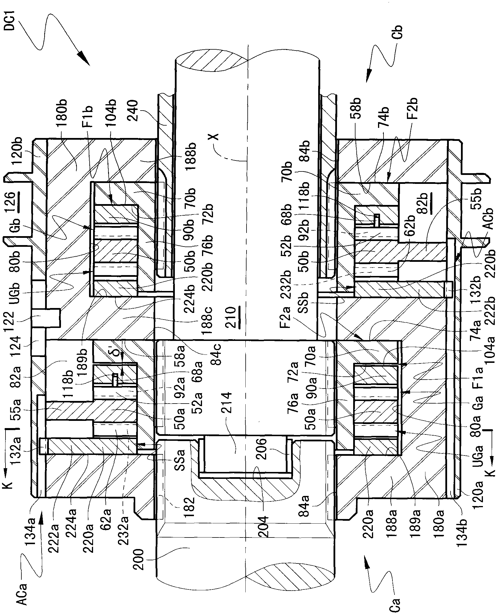
[0058] Figure 1~4 Shown is a shaft-to-shaft double clutch DC1 comprising two sub-clutches Ca and Cb rotating about an axis X and preferably rigidly connected. The two space clutch sub-clutches preferably have an almost identical structure, therefore, the left sub-clutch Ca will be described below as an example.

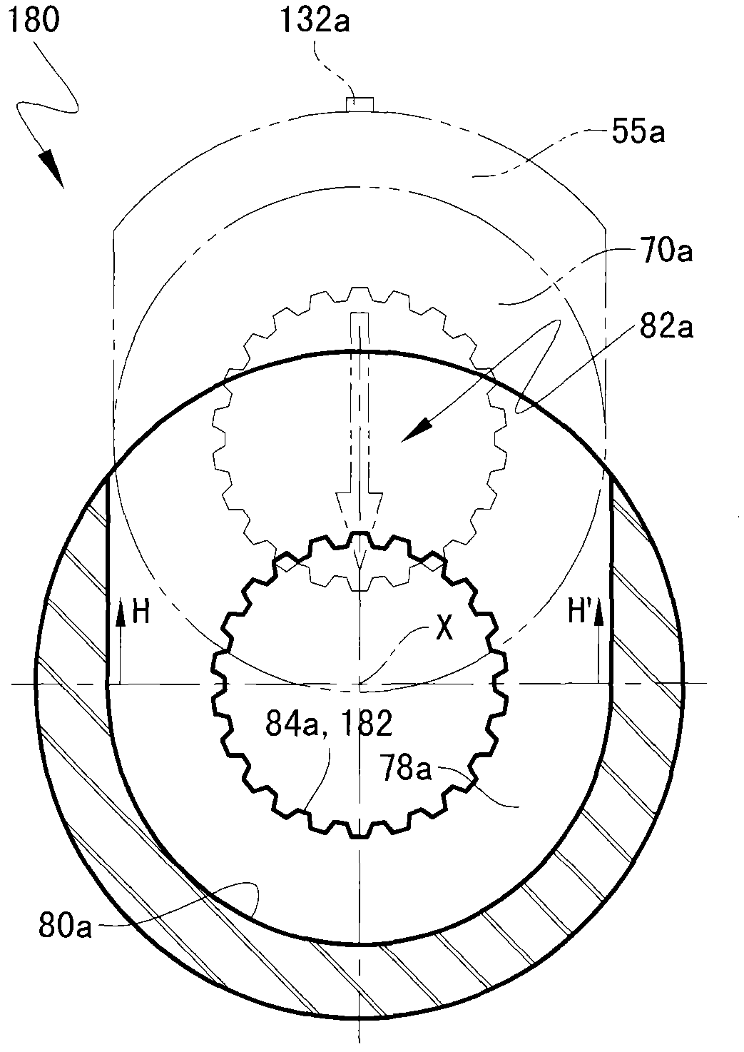
[0059] The force limiting element 180a formed around the axis X and having the function of sealing the axial force is preferably an annular bag-shaped member, and the axial middle part of the inner peripheral surface 84a, 84c formed around the axis X is coaxially provided with A disc-shaped annular circumferential groove 78a, which is preferably planar. The inner surface of about half of the circumferential groove 78a preferably extends to the outer peripheral surface of the force limiting element 180a along two mutually parallel tangential direction...

Embodiment 2

[0108] Embodiment 2: Tandem space wedging dual clutch DC3 that can be flexibly engaged

[0109] Such as Figure 6 As shown, dual clutch DC3 can be viewed as a hybrid variant of dual clutches DC1 and DC2, and optimally has a setting of λ' at least approximately equal to ξ'. Wherein, the guide 50 is provided with a force arm 55 to be non-rotatably connected with the force limiting element 180 to form a combined bag-shaped guide. Between the supporting end surfaces 51 and 189 of the guide member 50 and the force limiting element 180, there is an elastic element, such as a disc or diaphragm spring 100, so that the dual clutch DC3 has a friction-slip flexible engagement capability. In at least one radial through hole at corresponding positions on the inner surfaces 80 a and 80 b of the circumferential groove 78 , limiting pins 154 a and 154 b are respectively fixedly arranged. The inner radially protruding portions of the limiting pins can respectively axially interfere with the ...

Embodiment 3

[0112] Embodiment 3: Socket type space wedging dual clutch DC4 with mechanical stepless support mechanism

[0113] see Figure 7-11 , the dual clutch DC4 has a relatively small axial dimension relative to DC1. Among them, the two sub-clutches Ca and Cb are arranged in a radially inner and outer sleeve type. For this reason, the package housing that provides the sealing function of axial force is modified into an axial combined member, which includes a substantially annular force limiting element 160a provided with at least one arc-shaped protrusion 166, and a substantially annular force limiting element 160a provided with at least one screw hole. Force limiting element 160b. The screw 176 screwed into the threaded counterbore 183 on both sides of the top of each arc-shaped protrusion 166 fixes the force-limiting elements 160a and 160b into a rigid member, and defines the radial inner side of the arc-shaped protrusion 166. and two flat disc-shaped circumferential grooves on ...


PUM

PropertyMeasurementUnit
The inside diameter ofaaaaaaaaaa
Outer diameteraaaaaaaaaa
Axial widthaaaaaaaaaa

Abstract

A spatial wedge type double-clutch is characterized by being provided with a wedge-in control mechanism and two auto-excitation spatial wedge mechanisms / secondary clutches with high torque capacity. The control mechanism controls connection and separation of the double-clutch by operably controlling wedge-in and wedge-out of intermediate parts in the spatial wedge mechanisms. The wedge-in control mechanism most preferably comprises a mechanical rotational guide mechanism or a fluid closed chamber mechanism. Two trigger mechanisms require no maintaining energy, can be driven without high energy, and needs nearly zero energy in theory. The spatial wedge type double-clutch has overload slipping transmission capability automatically and adaptively. Meanwhile, power supply devices and driving devices are omitted, so that structure and operating procedure are simplified dramatically, cost is lowered, and higher reliability, miniaturization, lightweighting and long-distance wire controlled transmission are easy to be achieved.

Description

[0001] related application [0002] This application is a subordinate patent application of the Chinese patent applications 201010222712.X and 201020186785.3 named space wedging friction overrunning clutch proposed by the present applicant. The entire contents of the published prior two patent applications are hereby incorporated by reference. At the same time, this application claims the priority of the Chinese patent application 201010624902.4 with the same name proposed by the applicant. technical field [0003] The invention relates to a clutch device in the field of mechanical transmission, in particular but not only to an alternately working friction double clutch used in a power transmission system of a motor vehicle. Background technique [0004] Dual clutches used in dual clutch transmissions of motor vehicles have long been known. In addition to the necessary control device, the friction double clutch in the prior art also generally includes special energy supply...

Claims


Application Information

Patent Timeline
IPC IPC(8): F16D41/06
Inventor 洪涛
Owner 路亚科消防车辆制造有限公司
Why Eureka
Try Eureka