Thermal-force coupling fatigue test device and method

A technology of fatigue experiment and thermal fatigue, applied in the direction of measuring devices, instruments, scientific instruments, etc., can solve the complex service performance evaluation, brake disc and wheel material performance evaluation and life prediction uncertainty, brake disc and wheel material Issues such as performance improvement direction and target deviation

Inactive Publication Date: 2012-08-01
UNIV OF SCI & TECH BEIJING
View PDF4 Cites 38 Cited by
  • Summary
  • Abstract
  • Description
  • Claims
  • Application Information

AI Technical Summary

Problems solved by technology

The combined effect of these conditions makes the service performance evaluation of brake discs, wheels and rail materials extremely complicated. Traditional fatigue performance tests under single conditions, such as thermal fatigue experiments and stress fatigue experiments, cannot accurately characterize materials under real conditions. Therefore, it brings great uncertainty to the performance evaluation and life prediction of brake disc and wheel materials, and at the same time, the performance improvement direction and target deviation of brake disc and wheel materials
The main reason is that there is currently no good experimental device that can simultaneously satisfy cold-heat fatigue, stress fatigue and temperature gradients in line with actual conditions.

Method used


Image

  • Thermal-force coupling fatigue test device and method
  • Thermal-force coupling fatigue test device and method
  • Thermal-force coupling fatigue test device and method

Examples


Embodiment 1

[0024] Embodiment 1: Effect of cold-heat fatigue on material fatigue limit

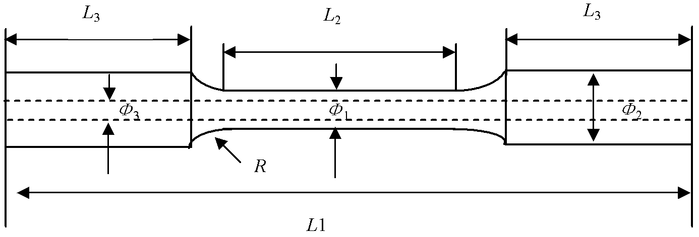
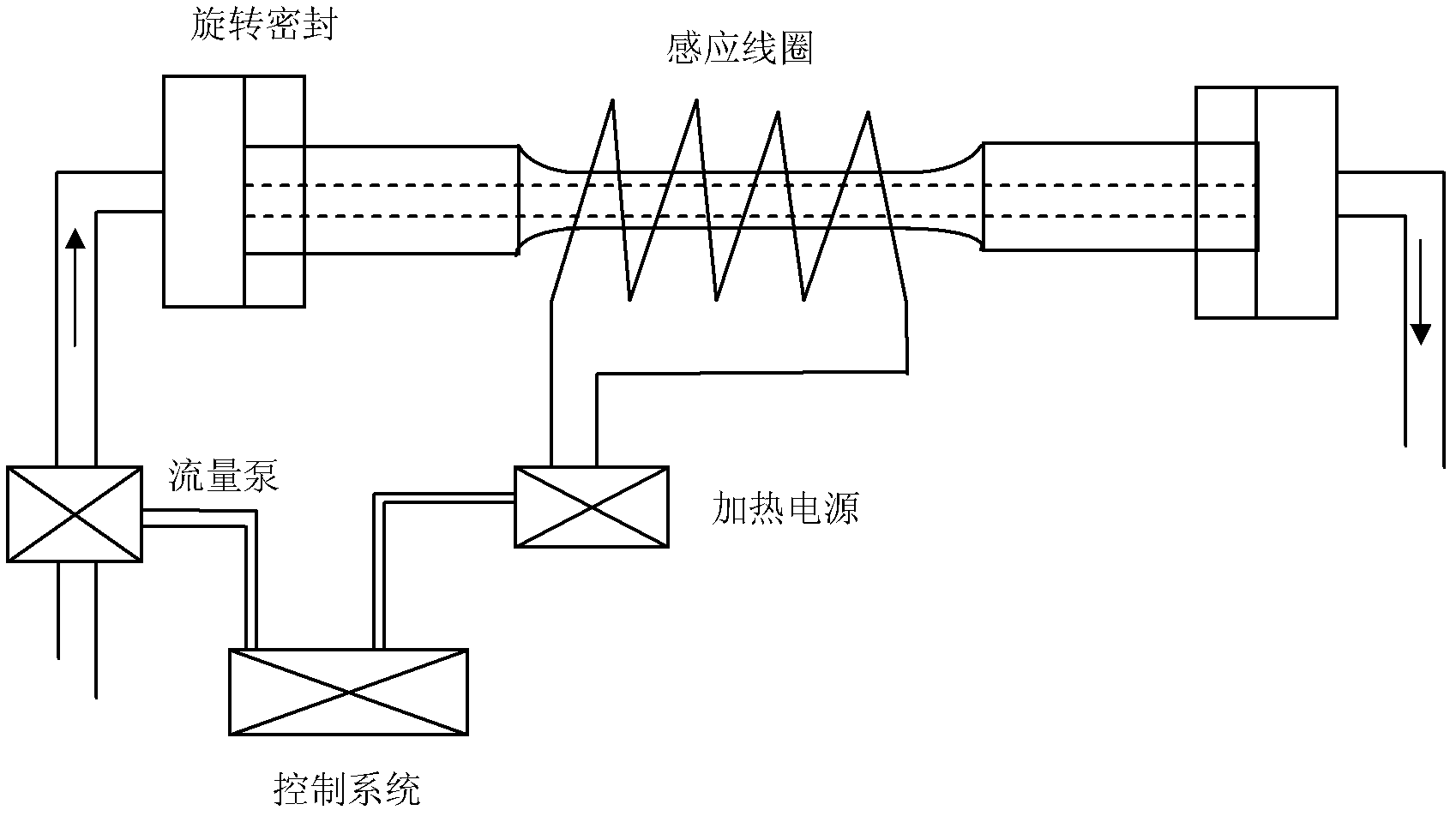
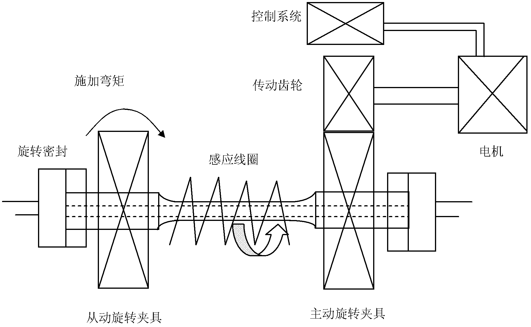
[0025] Machining the brake disc material into such figure 1 As shown in the sample, the sample is pressed figure 2 and image 3 The method shown is fixed on the experimental device, and the heating rate, holding time, cooling rate and cycle period of the material are set, such as Figure 4 shown. Stress fatigue under different stresses is carried out at the same time as cold-thermal fatigue, and the change curve of stress fatigue life with cyclic stress is obtained, namely S - N curves, such as Figure 5 shown. Adjust parameters for thermal fatigue, such as heating temperature T , the effect of thermal fatigue temperature on the fatigue performance of the material can be obtained, that is, the effect of thermal fatigue temperature on the fatigue limit can be obtained.

Embodiment 2

[0026] Example 2: Effect of Stress Fatigue on Material Thermal Fatigue Cracking Limit Temperature

[0027] Machining the brake disc material into such figure 1 As shown in the sample, the sample is pressed figure 2 and image 3 The method shown is fixed on the experimental device, and parameters such as the bending moment of the sample, that is, the maximum stress on the surface of the sample, and the fatigue frequency are set. While carrying out stress fatigue, carry out cold-heat fatigue experiments at different temperatures, and obtain the change curve of cold-heat fatigue life with cycle temperature, that is T - N curve. Varying stress fatigue parameters such as maximum stress S , the effect of fatigue stress on the thermal fatigue performance of the material can be obtained, such as Figure 6 shown.

[0028] To sum up, the present invention can well realize the testing of material properties and the research of failure mechanism under thermal-mechanical coupling...


PUM


Abstract

The invention relates to a thermal-force coupling fatigue test device and method, belonging to the field of metal material performance test and analysis. The device comprises a tested material test sample, a cold-thermal fatigue system and a stress fatigue system, wherein the test sample comprises a clamping section, a test section and a transition section; the cold-thermal fatigue system comprises a high frequency induction coil, a rotary seal device, a flow pump, a temperature sensor, a heating power supply, a cooling medium pipeline and a control system; and the stress fatigue system mainly comprises a driving rotating fixture, a driven rotating fixture, a transmission gear, a motor and a motor control system. The method comprises the following steps of: connecting and fixing the test sample with the cold-thermal fatigue system and the stress fatigue system, and carrying out cold-thermal fatigue while stress fatigues under different stresses are carried out to obtain a curve which shows variation of stress fatigue life along with cyclic stress; and adjusting parameters of the cold-thermal fatigue, thus influence of cold-thermal fatigue temperature to fatigue limit can be obtained.

Description

[0001] technical field [0002] The invention relates to a thermal-mechanical coupling fatigue experiment device and method, belonging to the field of performance testing and analysis of metal materials. [0003] Background technique [0004] With the rapid development of train speed and high-speed trains in our country, the safety of train operation has been widely valued. Wheels and brake discs are important structural components of high-speed trains, and their service performance is an important indicator related to train operation safety. During braking, especially emergency braking, high-speed trains suffer from cold-heat fatigue, frictional stress fatigue, and thermal stress caused by the temperature gradient on the brake disc cross-section caused by the friction between the brake disc and the brake pad. There is also frictional heat generation and frictional stress between the wheel and the rail, and their combined action will lead to thermal fatigue cracks on ...

Claims


Application Information

Patent Timeline
Patent Type & Authority Applications(China)
IPC IPC(8): G01N3/60G01N3/00G01N3/02
Inventor 任学冲孙凤艳文磊
Owner UNIV OF SCI & TECH BEIJING
Why Eureka
Try Eureka