Synchronous control system of step scanning photoetching machine based on VME (Virtual Mobile Engine) bus and synchronous control method thereof

A technology of synchronous control and step-scanning, applied in the directions of comprehensive factory control, electrical program control, and comprehensive factory control, which can solve the problems of large synchronization error and low lithography efficiency.

Inactive Publication Date: 2013-09-18
HARBIN INST OF TECH
View PDF3 Cites 1 Cited by
  • Summary
  • Abstract
  • Description
  • Claims
  • Application Information

AI Technical Summary

Problems solved by technology

[0004] The purpose of the present invention is to solve the problem of large synchronization error and low photolithography efficiency in the exposure process of the step and scan lithography machine, thus proposing a synchronous control system of the step and scan lithography machine based on the VME bus and the synchronization of the system Control Method

Method used


Image

  • Synchronous control system of step scanning photoetching machine based on VME (Virtual Mobile Engine) bus and synchronous control method thereof
  • Synchronous control system of step scanning photoetching machine based on VME (Virtual Mobile Engine) bus and synchronous control method thereof
  • Synchronous control system of step scanning photoetching machine based on VME (Virtual Mobile Engine) bus and synchronous control method thereof

Examples


specific Embodiment approach 1

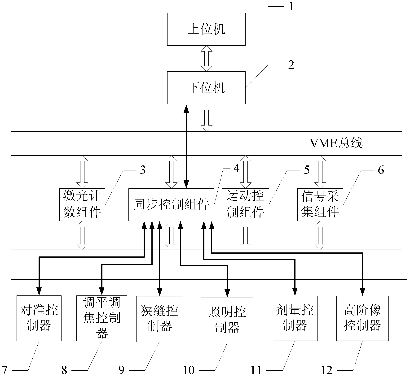
[0022] Specific implementation mode 1. Combination figure 1 Specifically explain this embodiment, the synchronous control system of the step-scan lithography machine based on VME bus, it comprises upper computer 1, lower computer 2, laser counting assembly 3, synchronous control assembly 4, motion control assembly 5 and VME bus, so The motion control assembly 5 described above is composed of a workpiece table controller and a mask table controller,

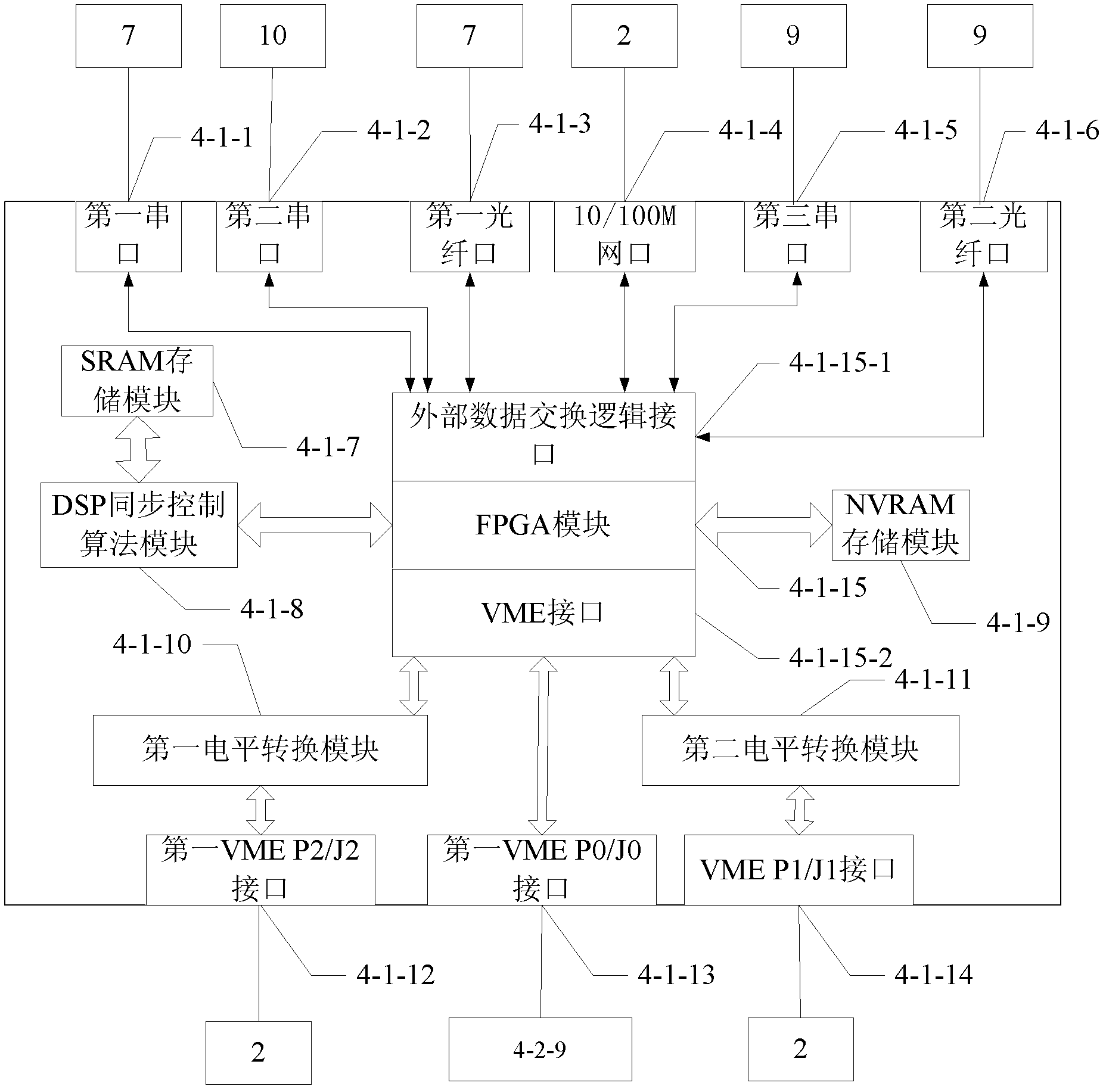
[0023] The VME bus includes a VME64 custom protocol bus and a VME64 standard bus, and the VME64 custom protocol bus is a user-defined interface of the P2 / J2 port, and the user-defined interface includes an address bus of a 7-bit laser counting component 3 , 36-bit laser counting component 3 data bus, 2 laser counting component 3 sampling signal lines, 1-bit laser counting component 3 clock signal line, 6-bit laser counting component 3 state transmission signal line, 1-bit motion control component 5 data reading signal line, the d...

specific Embodiment approach 2

[0026] Specific embodiment two, combine figure 1 Describe this embodiment in detail, the difference between this embodiment and the synchronous control system of the VME bus-based step-scan lithography machine described in Embodiment 1 is that it also includes a signal acquisition component 6, and the synchronous control component 4 automatically passes through VME64 Define the connection between the bus and the signal acquisition component 6 .

specific Embodiment approach 3

[0027] Specific embodiment three, combine figure 1 Describe this embodiment in detail. The difference between this embodiment and the synchronous control system of the VME bus-based step-scan lithography machine described in Embodiment 1 is that it also includes an alignment controller 7, a leveling and focusing controller 8. Slit controller 9, illumination controller 10, dose controller 11, high-order image controller 12, synchronous control component 4 and alignment controller 7, leveling and focusing controller 8, slit control through optical fiber respectively Controller 9, lighting controller 10, dose controller 11 and high-level image controller 12 are connected.


PUM


Abstract

The invention provides a synchronous control system of a step scanning photoetching machine based on a VME (Virtual Mobile Engine) bus and a synchronous control method thereof, which are to solve problems of large synchronization error and low photoetching efficiency in the exposure process of the step scanning photoetching machine. According to the invention, an upper machine is connected with a lower machine by an Ethernet; a synchronous control module is connected with the lower machine by a VME64 standard bus; the synchronous control module is connected with a laser counting module and a motion control module by VME64 user-defined protocol buses; a network port of the synchronous control module is connected with a network port of the lower machine by a network wire; and the VME bus comprises VME64 user-defined protocol buses and a VME64 standard bus. According to the invention, purposes of controlling and reducing the synchronization error in the step scanning process and increasing the photoetching efficiency are achieved. The synchronous control system and the synchronous control method, provided by the invention, are suitable for the field of scanning photoetching machines.

Description

technical field [0001] The invention relates to a synchronous control system, in particular to a synchronous control system of a VME bus-based step-scan photolithography machine and a synchronous control method of the system. Background technique [0002] The development of integrated circuits mainly depends on the development of semiconductor manufacturing equipment. With the advancement of technology, the integration level of silicon chips continues to increase, and the requirements for line width are getting higher and higher. At this stage, lithography has become the core technology of very large-scale integrated circuits, which plays a decisive role in the integration level of circuits. The lithography machine is a strategic task that integrates the latest research results in many fields of science and technology. [0003] With the increase of silicon chip size, high resolution and large field of view are required at the same time, the design cost of the objective lens...

Claims


Application Information

Patent Timeline
Patent Type & Authority Patents(China)
IPC IPC(8): G03F7/20G05B19/418
CPCY02P90/02
Inventor 刘杨郝中洋李聪王公峰闫华星彭贵勇陈兴林
Owner HARBIN INST OF TECH
Why Eureka
Try Eureka