
Waveguide-micro-strip integrated power distributor-synthesizer

A technology of success rate and distributor, which is applied to waveguide-type devices, electrical components, connecting devices, etc., can solve the problems of inability to be used in the field of solid-state power synthesis technology, inability to install solid-state devices, and insignificant effects, and achieve easy processing and realization. , compact structure, good phase consistency

Active Publication Date: 2012-08-01
CHENGDU SIMON ELECTRONICS TECH
View PDF3 Cites 19 Cited by
  • Summary
  • Abstract
  • Description
  • Claims
  • Application Information

AI Technical Summary

Problems solved by technology

The improvement lies in: 1. The structure of the probe is changed from 3 sections in literature [1] to 4 sections to obtain better broadband effect, but from the simulation results, the effect after improvement is not obvious; 2. Literature [2] ] In the power distribution structure, the space between the two probes in the literature [1] that is not filled with the medium is filled with the medium, and the multi-layer PCB technology is used for production
Since the space between the two probes is full of medium, it is impossible to install solid-state devices, and it cannot be used in the field of solid-state power synthesis technology
Therefore, the power divider in document [2] has no substantive and practical improvement compared to the power divider in document [1].

Method used


Image

  • Waveguide-micro-strip integrated power distributor-synthesizer
  • Waveguide-micro-strip integrated power distributor-synthesizer
  • Waveguide-micro-strip integrated power distributor-synthesizer

Examples


Embodiment Construction

[0014] The present invention will be further described below in conjunction with the accompanying drawings and specific embodiments.

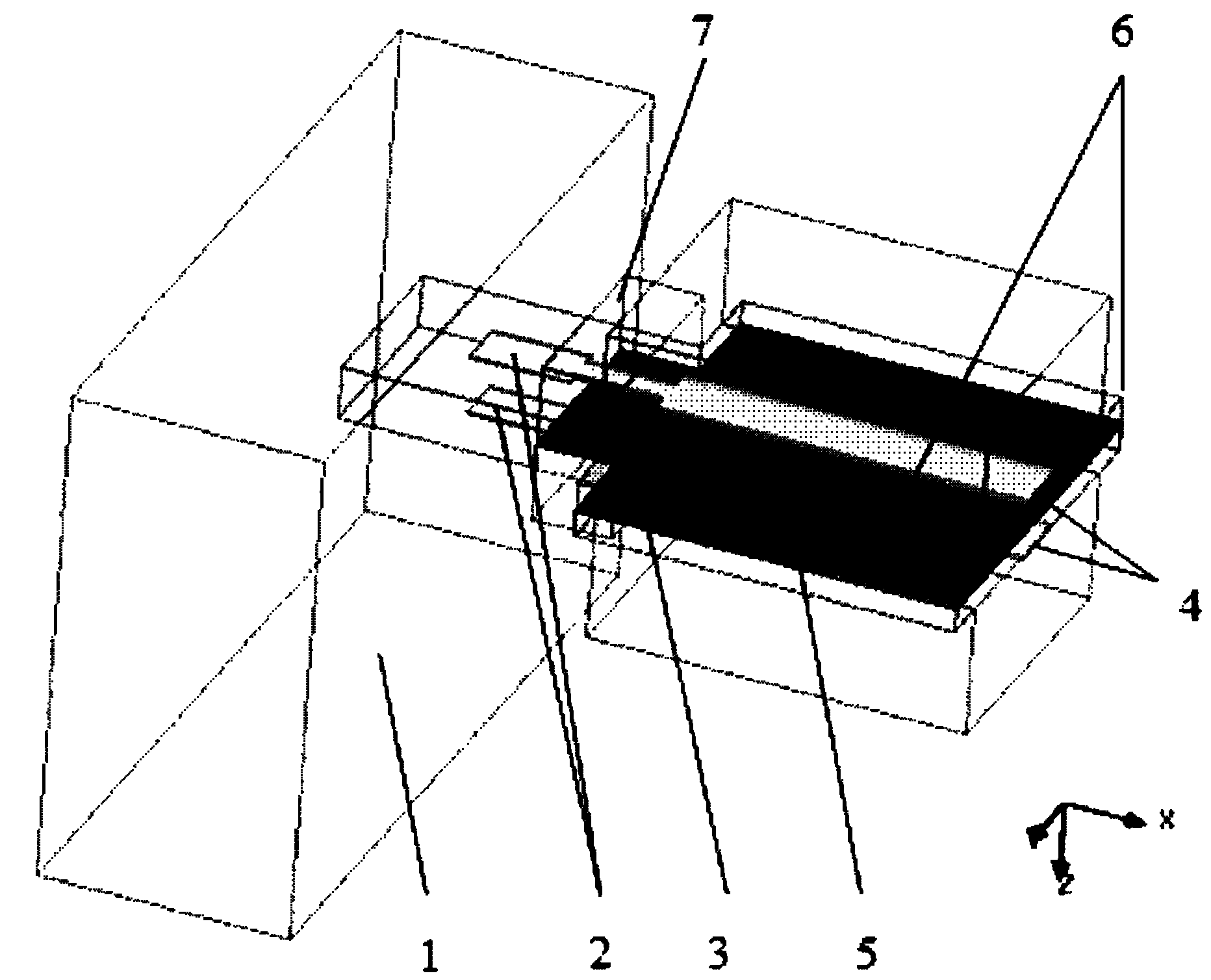
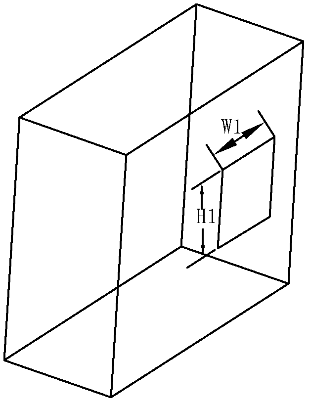
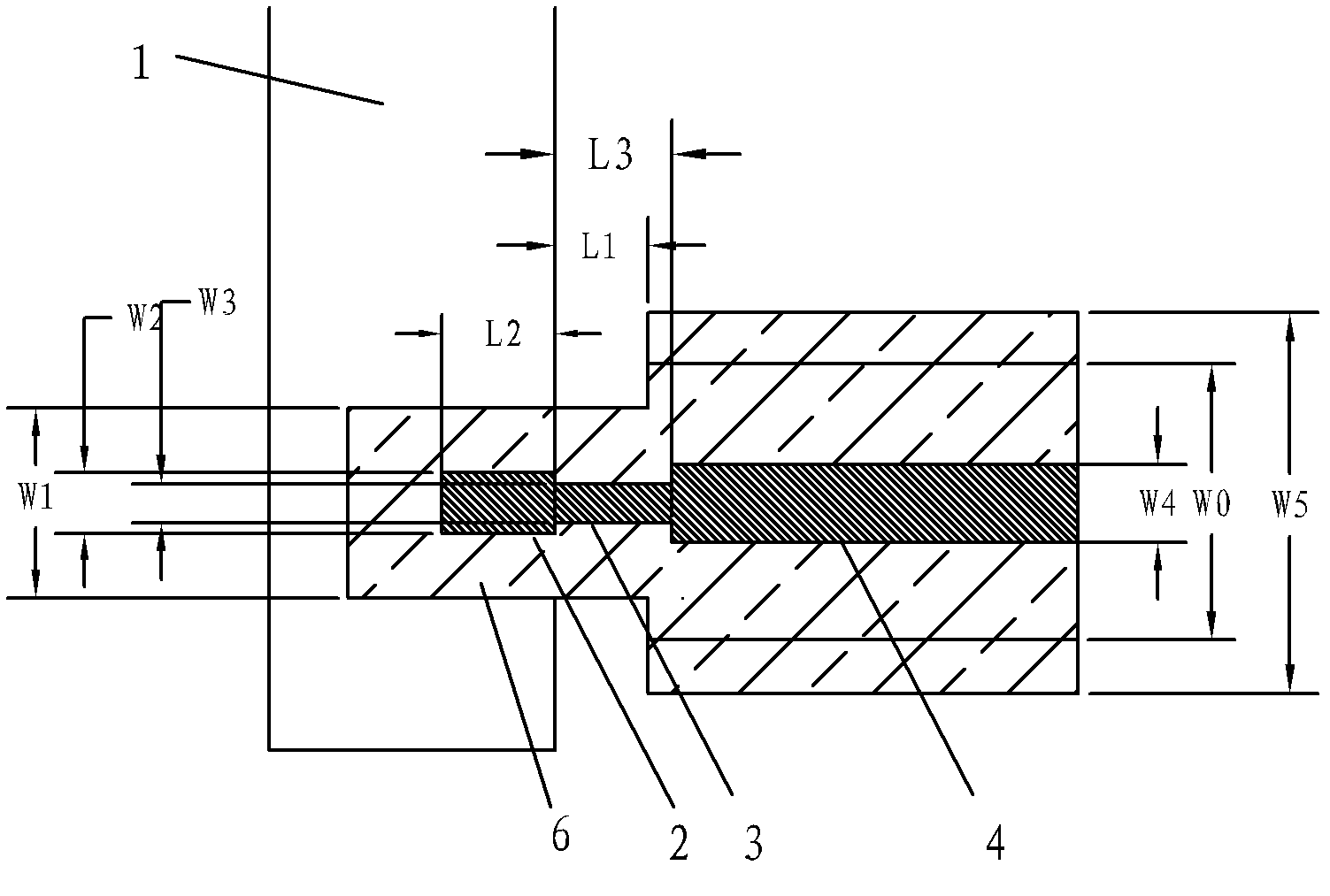
[0015] Such as figure 1 and figure 2 As shown, the waveguide-microstrip integrated power divider and combiner includes a rectangular waveguide 1, a dielectric substrate 6, and a common ground 5 embedded in the dielectric substrate 6, which is symmetrical with the common ground 5 and attached to the upper surface and the lower surface of the dielectric substrate 6. Two microstrip probes 2 on the surface, the two microstrip probes 2 are respectively connected to two groups of microstrip line impedance transformation sections 3 and two 50-ohm microstrip transmission lines 4 in sequence to form two groups of parallel and common ground 5 symmetrical microstrip lines respectively located on the upper surface and the lower surface of the dielectric substrate 6, the two microstrip probes 2 are vertically inserted into the rectangular waveguide 1 from...


PUM


Abstract

The invention relates to a waveguide-micro-strip integrated power distributor-synthesizer. The waveguide-micro-strip integrated power distributor-synthesizer comprises a rectangular waveguide, a medium substrate, a common land being inserted into the medium substrate and two micro-strip probes, wherein the two micro-strip probes are symmetric to each other about the common land and are respectively attached on the upper surface and the lower surface of the medium substrate, the two micro-strip probes are respectively and sequentially connected with two groups of micro-strip line impedance variable sections and two micro-strip transmission lines to form two parallel groups of micro-strip lines which are symmetric to each other about the common land and are respectively located on the upper surface and the lower surface of the medium substrate, the two micro-strip probes are vertically plugged into the rectangular waveguide from an opening on the side wall of a wide edge of the rectangular waveguide along a surface E of the rectangular waveguide, the plugging positions of the two micro-strip probes are symmetric to each other about a central surface of the wide edge of the rectangular waveguide; and a theoretical distance from the central line of each micro-strip probe to a waveguide short-circuited surface in the transmission direction of the rectangular waveguide is a quarter of one waveguide wavelength. The waveguide-micro-strip integrated power distributor-synthesizer has beneficial effects of low loss, wide band, good consistence of amplitudes and phases among different branches, compact structure and easiness in realization.

Description

technical field [0001] The invention belongs to the technical field of microwave and millimeter wave solid-state power synthesis; in particular, it relates to millimeter wave and submillimeter wave band broadband low loss waveguide-microstrip integrated power distribution and synthesis technology. Background technique [0002] With the increase of operating frequency, due to material and process reasons, the output capability of solid-state devices decreases exponentially. For example, the output capability of a single device in the eight millimeter wave frequency band is about 5W, and the output capability of a solid state single device in the three millimeter wave frequency band is only about 100-200mW. It is far from meeting the system requirements. Power combining technology is an effective means to solve the insufficient output capability of a single device and obtain higher power. The power combination is actually the vector superposition of each combined signal, whic...

Claims


Application Information

Patent Timeline
IPC IPC(8): H01P5/08
Inventor 谢小强赵翔詹铭周吴永伦周睿周沛翰谢凌霄
Owner CHENGDU SIMON ELECTRONICS TECH
Learn More