Energy recovery type lifting hydraulic system for hoisting and conveying machine

A technology of lifting and transporting machinery and energy recovery, applied in the field of lifting hydraulic system, can solve the problems of high cost and complicated control, and achieve the effect of low cost, simple system and avoiding impact

Inactive Publication Date: 2012-08-08
ANHUI HELI CO LTD
View PDF5 Cites 11 Cited by
  • Summary
  • Abstract
  • Description
  • Claims
  • Application Information

AI Technical Summary

Problems solved by technology

The foreign forklift or crane lowering energy recovery system meets the lifting and lowering oil circuit switching requirements by connecting one or two sets of electromagnetic reversing valves, which is costly and complicated to control.

Method used


Image

  • Energy recovery type lifting hydraulic system for hoisting and conveying machine
  • Energy recovery type lifting hydraulic system for hoisting and conveying machine

Examples


Embodiment

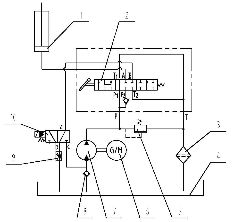
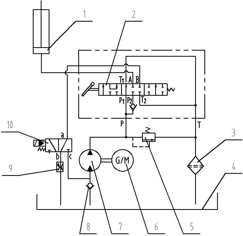
[0017] see figure 1 An energy recovery lifting hydraulic system for hoisting and transporting machinery includes a lifting cylinder 1 and a lifting reversing valve 2 . The lifting reversing valve 2 is a three-position, six-way reversing valve, and the first oil inlet P1 and the second oil inlet P2 of the lifting reversing valve 2 are connected to the oil inlet of the lifting reversing valve 2 through a three-way pipe. P; the first oil outlet T1 and the second oil outlet T2 of the lifting reversing valve 2 are connected to the oil return port T through a three-way pipe; the first working oil port A of the lifting reversing valve 2 is connected to the lifting cylinder 1, The second working oil port B of the lifting reversing valve 2 is connected with the oil inlet a of the directional control valve 10, and the directional control valve 10 is a two-position three-way electromagnetic directional valve (it can also be a two-position three-way electro-hydraulic reversing valve). va...


PUM


Abstract

The invention relates to an energy recovery type lifting hydraulic system for a hoisting and conveying machine. A lifting reversing valve of the energy recovery type lifting hydraulic system is a three-position and six-way reversing valve, wherein an oil inlet P is communicated to a first oil inlet P1 and a second oil inlet P2 of the lifting reversing valve through a three-way pipe; an oil return port T is communicated to a first oil outlet T1 and a second oil outlet T2 of the lifting reversing valve through a three-way pipe; a lifting oil cylinder is communicated to a first work oil port A; an oil inlet a of a direction control valve is communicated to a second work oil port B; the direction control valve is a two-position and three-way electromagnetic reversing valve or a two-position and three-way electro-hydraulic reversing valve; the oil inlet P and an inlet of a safety valve are communicated to an oil outlet of the oil pump through a three-way pipe; a hydraulic oil tank is communicated to an oil suction port of the oil pump through a one-way valve; the oil return port T is communicated to an outlet of the safety valve; the oil tank is communicated to a first oil outlet b of the direction control valve through a speed limiting valve; the oil suction port of the oil pump is communicated to a second oil outlet c of the direction control valve; and the one-way valve is arranged on the oil suction port of the oil pump. According to the energy recovery type lifting hydraulic system disclosed by the invention, the recovery efficiency of potential energy is 65 to 75 percent.

Description

technical field [0001] The invention belongs to the technical field of lifting and transporting machinery hydraulic systems, and in particular relates to lifting hydraulic systems of forklifts and cranes. Background technique [0002] In the lifting hydraulic system of common hoisting and transporting machinery (such as the lifting hydraulic system of forklifts, cranes, etc.), no matter what control principle is used, one thing is common, that is, in the process of lowering the weight, various knots are used Flow mode to control the falling speed of heavy objects. In this process, the gravitational potential energy is all converted into heat energy through the throttle valve, which will cause the temperature of the hydraulic system to rise, affecting the reliability of the system and components and the working efficiency of the vehicle. With the increasingly tense international energy supply and the increasing awareness of environmental protection around the world, green an...

Claims


Application Information

Patent Timeline
Patent Type & Authority Applications(China)
IPC IPC(8): F15B21/14B66C13/20B66F9/22
Inventor 温跃清马庆丰田原张丽吴信丽周齐齐
Owner ANHUI HELI CO LTD
Why Eureka
Try Eureka