Stack type battery and method of manufacturing the same

A stacked, stacked electrode technology, which is applied in secondary battery manufacturing, secondary batteries, lithium batteries, etc., can solve problems such as damage to composite exterior bodies, small holes, and easy short circuits

Active Publication Date: 2012-08-08
PANASONIC ENERGY CO LTD MORIGUCHI SHI
View PDF5 Cites 28 Cited by
  • Summary
  • Abstract
  • Description
  • Claims
  • Application Information

AI Technical Summary

Problems solved by technology

[0012] However, for the structure in which the positive and negative current collector tabs are bent as described above, the positive and negative current collector tabs are easily deformed and protrude in the extending direction due to the property that the bent portion expands and returns to its original shape. , so there is a problem that the position of the positive and negative collector terminals protruding from the outer casing is unstable
In addition, for example, in Patent Document 1 Figure 4 and Figure 5 As shown, resin 142 is applied to the positive and negative current collector terminals joined to the positive and negative current collector tabs so as to be sandwiched between the thermally welded parts (sealed parts) of the composite exterior body, thereby preventing electrolysis. Liquid leakage and short circuit at this part, in the manufacturing process, when the positive and negative electrode current collector tabs are deformed so as to protrude in the extending direction as described above, the resin 142 is also extruded and removed from the composite package. The thermally welded part of the body is detached, so that the positive and negative collector terminals are directly in contact with the composite outer body, and there is a problem that a short circuit is likely to occur
[0013] In addition, if the bent portion of the positive and negative electrode current collector tabs is easy to expand as described above, when the composite exterior body is decompressed and sealed, the composite exterior can be opened while the bent positive and negative electrode current collector tabs are opened. As a result, in this part, the composite exterior body is sunken inward to form wrinkles, so the composite exterior body is also damaged and short circuits are likely to occur, and cracks may occur on the composite exterior body, resulting in reduced durability or damage to the composite exterior body. small hole
[0014] Here, according to the structure shown in the above-mentioned patent document 1 to patent document 2, an insulating tape 147 is also arranged on the inner side (valley side) of the bent portion of the positive and negative electrode current collector tabs to become the same as the positive and negative electrode current collector tabs. The common bending structure, so the original shape recovery of the insulating tape 147 promotes the deformation of the positive and negative current collector tabs protruding in the extending direction, resulting in easier deformation
At this time, if the insulating tape 147 arranged on the inner side (valley side) of the bent portion is thin, the original shape restoration property can be weakened, even if the deformation of the positive and negative electrode current collector tabs protruding in the extending direction can be reduced accordingly, as long as the If deformation cannot be suppressed, it can never be called a sufficient countermeasure

Method used


Image

  • Stack type battery and method of manufacturing the same
  • Stack type battery and method of manufacturing the same
  • Stack type battery and method of manufacturing the same

Examples


no. 1 approach

[0107] [production of positive electrode]

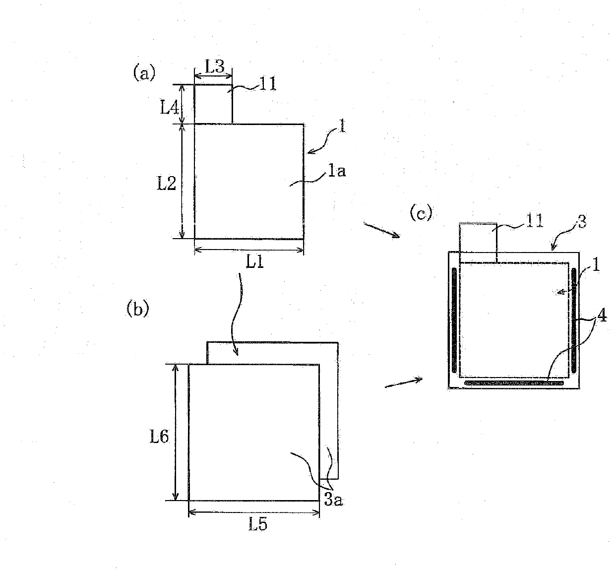
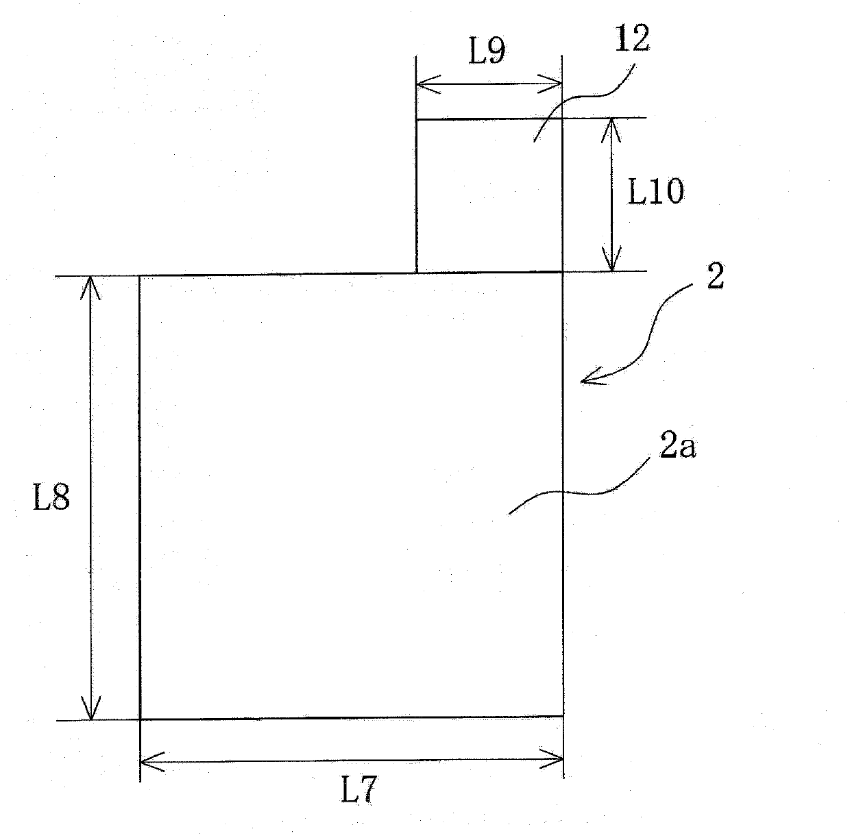
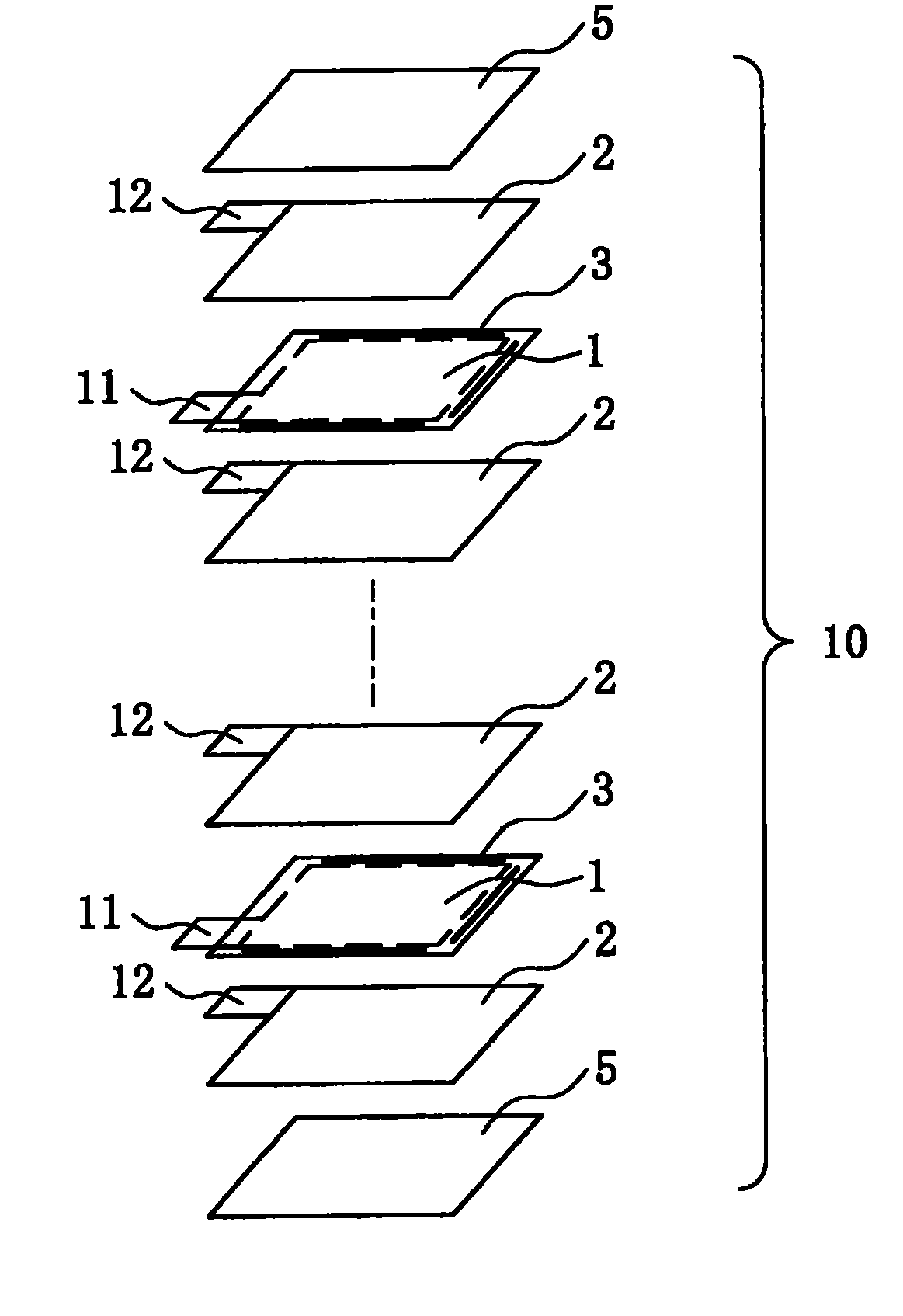
[0108] 90% by mass of LiCoO as the positive electrode active material 2 , 5% by mass of carbon black as a conductive agent, 5% by mass of polyvinylidene fluoride as a binder, and N-methyl-2-pyrrolidone (NMP) solution as a solvent were mixed to prepare a positive electrode slurry. This positive electrode slurry was applied to both surfaces of an aluminum foil (thickness: 15 μm) as a positive electrode current collector. Then, after drying the solvent by heating and compressing it to a thickness of 0.1mm by rollers, as figure 1 As shown in (a), the positive electrode plate 1 having the positive electrode active material layer 1 a on both surfaces was produced by cutting into a width L1 = 85 mm and a height L2 = 85 mm. At this time, make the active material uncoated part of width L3=30mm, height L4=20mm from one end of one side extending along the width L1 direction of the positive electrode plate 1 ( figure 1 In (a), the left end ...


PUM

PropertyMeasurementUnit
thicknessaaaaaaaaaa
thicknessaaaaaaaaaa
thicknessaaaaaaaaaa

Abstract

A stack type battery (A1) has a stacked electrode assembly (10) having a plurality of positive electrode plates having respective positive electrode current collector leads (11) protruding therefrom, a plurality of negative electrode plates (2) having respective negative electrode current collector leads protruding therefrom, and separators (3a) interposed between the positive electrode plates (1) and the negative electrode plates (2). The stacked positive electrode current collector leads (11) and the stacked negative electrode current collector leads are bundled at one stacking direction-wise side of the stacked electrode assembly (10), and a portion of the bundled leads is bent toward the other stacking direction-wise side. The positive electrode current collector leads (11) or the negative electrode current collector leads are provided with a fastening tape (46) for retaining a portion of the bundled leads in a folded shape so as to be pulled toward the positive and negative electrode plates (1, 2).

Description

technical field [0001] The invention relates to a stacked battery and a manufacturing method thereof. Background technique [0002] In recent years, batteries have been used not only as power sources for mobile information terminals such as mobile phones, personal computers, and PDAs, but also for robots, electric vehicles, and backup power supplies, and further increases in capacity have been demanded. In response to such demands, especially in the field of secondary batteries, lithium batteries are widely used as the above-mentioned driving power sources because of their high energy density and high capacity. [0003] The battery form of such a lithium ion battery generally includes a spiral lithium ion battery in which a spiral electrode body is enclosed in an outer casing, a laminated electrode body in which a plurality of square electrodes are stacked, and an outer casing by welding. A laminated lithium-ion battery (laminated prismatic lithium-ion battery) in a composi...

Claims


Application Information

Patent Timeline
Patent Type & Authority Applications(China)
IPC IPC(8): H01M2/16H01M10/0525H01M10/0583H01M50/528H01M50/533H01M50/54
CPCH01M2/22H01M10/0436H01M2/266Y02E60/122H01M10/0585H01M10/0413H01M10/052H01M10/0468H01M10/0583Y10T29/49108Y10T29/4911Y02E60/10H01M50/528H01M50/54Y02P70/50H01M50/533
Inventor 新屋敷昌孝藤原雅之
Owner PANASONIC ENERGY CO LTD MORIGUCHI SHI
Why Eureka
Try Eureka