Artificial structure-based multi-frequency circular polarizer

A circular polarizer and artificial structure technology, applied in waveguide-type devices, electrical components, circuits, etc., can solve the problems of large volume, complex structure of circular polarizer, less working frequency band, etc., and achieve multiple working frequency points, more Transmission wave polarization mode, simple structure effect

Active Publication Date: 2012-08-08
INST OF OPTICS & ELECTRONICS - CHINESE ACAD OF SCI
View PDF2 Cites 9 Cited by
  • Summary
  • Abstract
  • Description
  • Claims
  • Application Information

AI Technical Summary

Problems solved by technology

[0004] The technical problem to be solved by the present invention is: to overcome the disadvantages of existing circular polarizers such as complex structure, few working frequency bands, and large volume; to propose a multi-frequency circular polar

Method used


Image

  • Artificial structure-based multi-frequency circular polarizer
  • Artificial structure-based multi-frequency circular polarizer
  • Artificial structure-based multi-frequency circular polarizer

Examples


Embodiment Construction

[0020] The present invention will be described in detail below in conjunction with the accompanying drawings and specific embodiments, but the scope of protection of the present invention is not limited to the following examples, but should include all content in the claims. Moreover, those skilled in the art can realize all the content in the claims from the following embodiment.

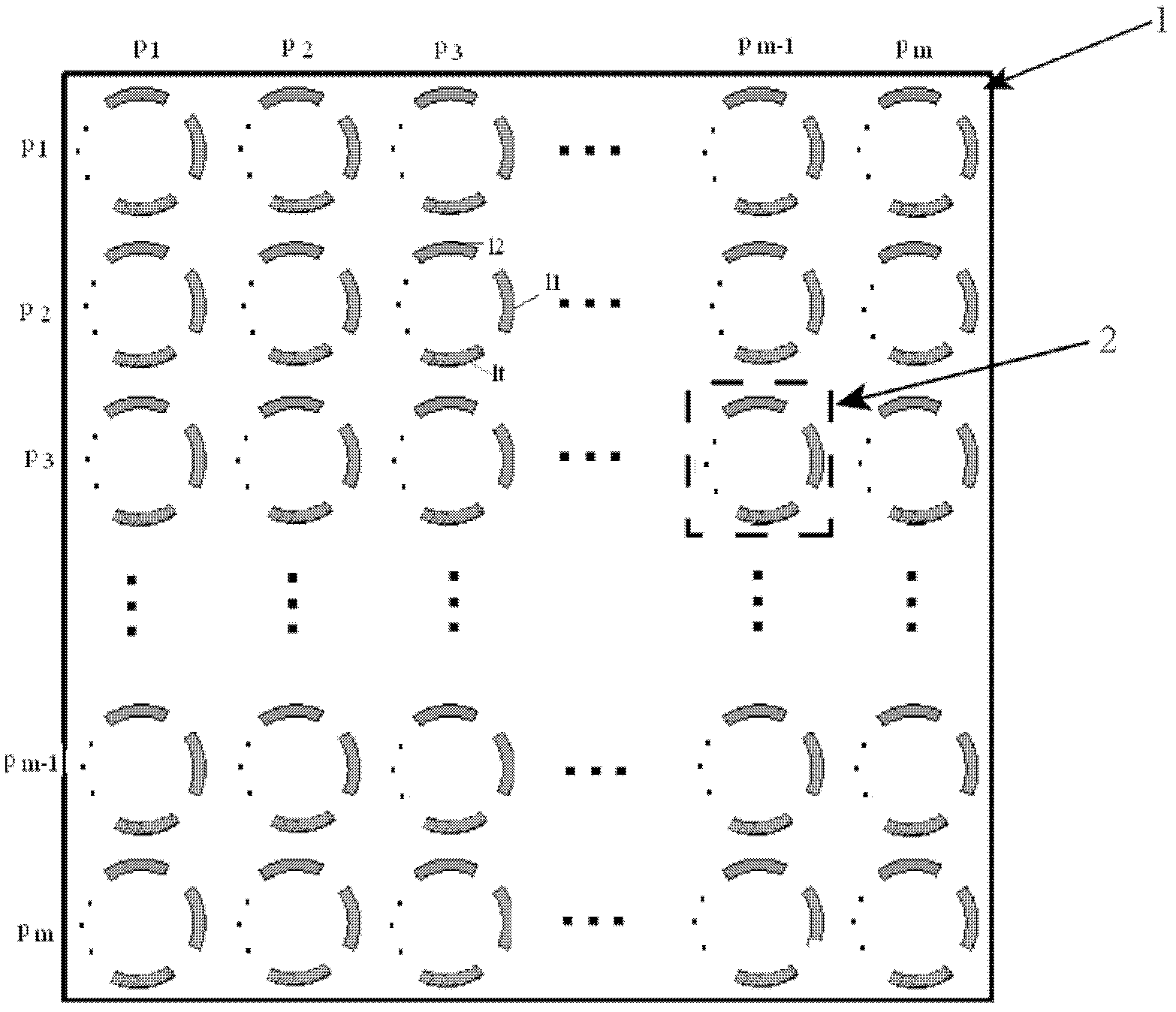
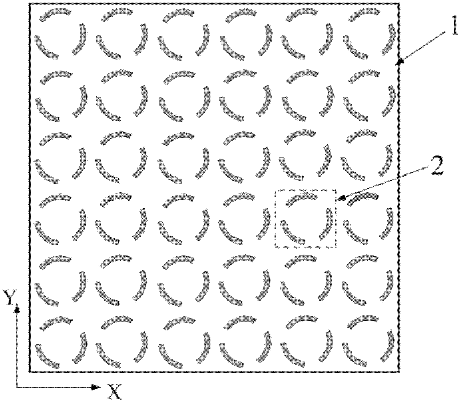
[0021] figure 1 Among them, 1 represents the rectangular dielectric substrate, 2 represents the periodic arc-shaped metal wire structure fabricated on the rectangular dielectric substrate 1, p1, ..., pm represent the first, ..., m periods of the horizontal and vertical directions on the rectangular dielectric substrate 1 The circular arc-shaped metal wire structure, l1, ..., lt represent the first, ..., t circular arc-shaped metal wire structures in the periodic arc-shaped metal wire structure 2.

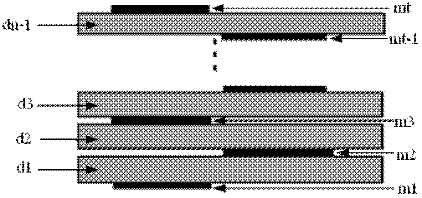
[0022] figure 2 Among them, d1, ..., dn-1 represent the 1st, ..., n-1 layers in the n-1 layer rect...


PUM


Abstract

The invention discloses an artificial structure-based multi-frequency circular polarizer, which comprises n-1 (n is an integer of greater than or equal to 3.) layers of rectangular dielectric substrates and periodic circular arc metal wire structures, wherein the periodic circular arc metal wire structures are manufactured on the n-1 layers of rectangular dielectric substrates in the transverse direction and the longitudinal direction; each periodic circular arc metal wire structure comprises t (t=n) circular arc metal wires; t circular arc metal wires are arranged on the first, the second,... ..., the nth faces of the n-1 layers of rectangular dielectric substrates respectively; seen from the direction perpendicular to the plane where the rectangular dielectric substrates are positioned, t circular arc metal wires form t equal parts of a concentric circle; the width of the t circular arc metal wires and the corresponding central angle theta are the same; and the central angle corresponding to a gap between every two circular arc metal wires is also the same. When linear polarization wave with an electric field polarization direction parallel to the longitudinal boundary of the circular polarizer enters in the direction perpendicular to the plane where the rectangular dielectric substrates are positioned, the circular polarizer can convert the incident linear polarization wave into circular polarization transmitted wave with different rotation directions at k (k=t) different frequency points.

Description

technical field [0001] The invention relates to a multi-frequency circular polarizer, in particular to a multi-frequency circular polarizer based on an artificial structure. Background technique [0002] Circularly polarized waves have the advantages of rotation orthogonality, can suppress rain and fog interference, and resist multipath effects, so they are widely used in satellite communications, radar, etc. A circular polarizer is a common device used to excite circularly polarized waves. Traditional circular polarizers include waveguide circular polarizers, grid circular polarizers, and meander line circular polarizers. The waveguide circular polarizer uses a polarization splitter in the waveguide to decompose the incident ray polarized wave into two orthogonal and equal-amplitude linear polarization modes, and then adjust these two modes separately to make a 90° between them The phase difference, so as to realize the conversion of linear polarized wave to circular pola...

Claims


Application Information

Patent Timeline
IPC IPC(8): H01P1/17
Inventor 罗先刚黄成冯沁蒲明博马晓亮
Owner INST OF OPTICS & ELECTRONICS - CHINESE ACAD OF SCI
Why Eureka
Try Eureka