Thermal treatment method for hinge pin shaft of hydraulic support

A heat treatment method and hydraulic support technology, applied in the field of heat treatment, can solve problems such as brittle fracture

Inactive Publication Date: 2012-08-15
CHINA COAL BEIJING COAL MINING MACHINERY
View PDF2 Cites 4 Cited by
  • Summary
  • Abstract
  • Description
  • Claims
  • Application Information

AI Technical Summary

Problems solved by technology

Although the problem of wear resistance on the outer surface of the outer

Method used


Image

  • Thermal treatment method for hinge pin shaft of hydraulic support
  • Thermal treatment method for hinge pin shaft of hydraulic support

Examples


specific Embodiment

[0022] Tempered hardness HB240~HB300, surface hardness HRC44~HRC48.

[0023] Medium-frequency induction heating: the current frequency is 500-10000Hz (Hertz), and the effective hardening depth is 2-10mm (millimeters). Effect, the induced current accumulates on the surface of the material to generate heat, reaches the phase transition temperature, and quenches to achieve the purpose of quenching. It not only changes its structure and performance, but also improves the surface hardness and wear resistance of parts. With the pre-heat-treated heart tissue, higher fatigue strength and toughness are obtained.

[0024] The applicant found that the austenitization of steel is carried out at a relatively high degree of superheat (80-150°C above Ac3), and there are many crystal nuclei, which are not easy to grow. After quenching, the structure is fine cryptocrystalline martensite, and the brittleness is low; After the surface layer is quenched to obtain martensite, the volume expansio...


PUM


Abstract

The invention discloses a thermal treatment method for a hinge pin shaft of a hydraulic support. The method comprises the following steps of: tempering the pin shaft to obtain a tempered sorbite; and performing surface quenching on the pin shaft at the temperature of between 80 and 150 DEG C above Ac3 to obtain a fine cryptocrystalline martensite. By utilizing the method, the surface of the part has certain hardness, the part has abrasion resistance and fatigue resistance, and the core has enough strength and toughness.

Description

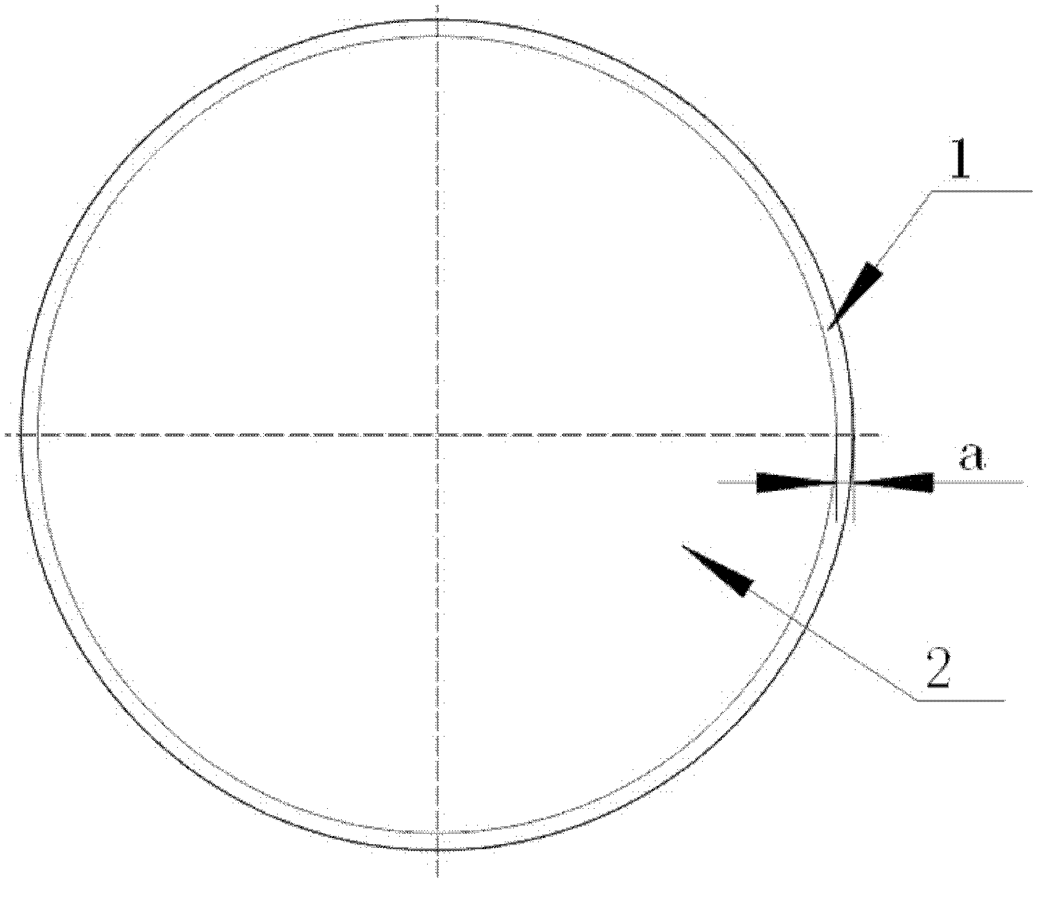
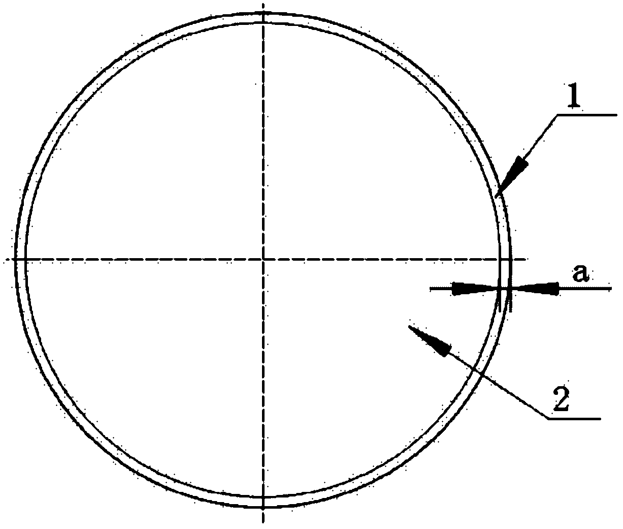
technical field [0001] The invention relates to a heat treatment technology for key components of an underground hydraulic support in a coal mine, in particular to a heat treatment method for a hinge pin of a hydraulic support. Background technique [0002] The hinge pin used for the hydraulic support is the key part connecting the four-bar linkage mechanism, and the force is relatively complicated, mainly bending and shearing. The materials are mainly alloy structural steels such as 35CrMoSiA and 30CrMnTi. [0003] In the past, the process method used was to carry out overall quenching and tempering treatment only on the hinge pin shaft. The design strength met the requirements of use, and the phenomenon of groove marks often appeared on the outer circular surface. In order to solve the problem of insufficient surface hardness, the quenched and tempered hardness has been increased to reach above HB300. Although the problem of wear resistance of the outer circle surface ha...

Claims


Application Information

Patent Timeline
IPC IPC(8): C21D9/28C21D1/25C21D1/10
CPCY02P10/25
Inventor 王绍立王亮忠樊哲亮
Owner CHINA COAL BEIJING COAL MINING MACHINERY
Why Eureka
Try Eureka