Check patentability & draft patents in minutes with Patsnap Eureka AI!

Rotational speed signal conditioning circuit of magnetoelectric sensor

A magnetoelectric sensor and speed signal technology, applied in pulse shaping and other directions, can solve problems such as low reliability, waveform distortion, and component damage, and achieve the effects of improving circuit reliability, improving anti-interference performance, and suppressing waveform distortion

Inactive Publication Date: 2012-08-15
SHANDONG UNIV
View PDF5 Cites 11 Cited by
  • Summary
  • Abstract
  • Description
  • Claims
  • Application Information

AI Technical Summary

Problems solved by technology

[0002] The conventional processing method of magnetoelectric sensor signals is to use a comparator to shape the input waveform, but the sensor signal is affected by factors such as installation clearance, speed and sensor model, and the reference voltage of the comparator cannot be determined, especially for magnetoelectric sensors in internal combustion engines. The above method cannot eliminate the signal glitch caused by the vibration of the engine gear plate, which makes the waveform distorted after the output of the comparator, and the traditional method is to eliminate the negative half cycle signal of the magnetoelectric sensor, and connect a diode in series when the signal is input, so that the circuit can only adapt to the amplitude above 1V signal shaping
Some people combine the single-chip microcomputer control system to collect the original signal through the single-chip A / D, and then determine the reference voltage of the comparator, and then adjust the speed signal, but the cost of this method is relatively high, and a complex single-chip computer system is required. It will exceed the maximum input voltage allowed by the comparator, causing damage to components and low reliability

Method used


Image

  • Rotational speed signal conditioning circuit of magnetoelectric sensor
  • Rotational speed signal conditioning circuit of magnetoelectric sensor

Examples


Embodiment Construction

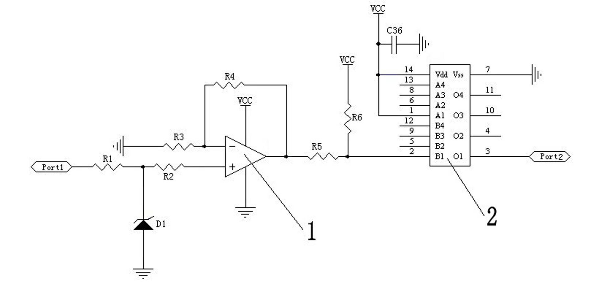
[0011] Attached below figure 1 The present invention will be further described.

[0012] The speed signal conditioning circuit of the magnetoelectric sensor includes Port1 interface for sinusoidal signal input of the magnetoelectric sensor, operational amplifier 1, hysteresis comparator and Port2 interface for outputting the square wave signal of the speed. Diode D1 and resistor R2 are connected to the non-inverting input terminal of operational amplifier 1, resistor R3 is connected to the inverting input terminal of operational amplifier 1, resistor R4 is connected to the inverting input terminal and output terminal of operational amplifier 1, and the hysteresis comparator passes through the resistor R5 and resistor R6 are connected to the output terminal of the operational amplifier 1, and the Port2 interface is connected to the hysteresis comparator. The sinusoidal voltage signal induced by the magnetoelectric sensor is amplified by the operational amplifier 1 after being ...


PUM


Abstract

The invention relates to a rotational speed signal conditioning circuit of a magnetoelectric sensor. The rotational speed signal conditioning circuit comprises a Port 1 interface for inputting sine signals, an operational amplifier, a hysteresis comparator and a Port 2 interface for outputting rotational speed square wave signals, wherein the Port 1 interface is connected with the in-phase input end of the operational amplifier via a resistor R1, a voltage stabilizing diode D1 and a resistor R2, a resistor R3 is connected with the reverse-phase input end of the operational amplifier, a resistor R4 is connected with the reverse-phase input end and the output end of the operational amplifier, the hysteresis comparator is connected with the output end of the operational amplifier via a resistor R5 and a resistor R6, and the Port 2 interface is connected with the hysteresis comparator. The circuit can be used for still conditioning the stable square wave signals when the original signals of the magnetoelectric sensor are above 30V, and solving the problem that components are easy to damage due to large signal amplitude. The circuit can be used for solving the problem that the diodes which are connected in series can not be conditioned due to the smaller signal amplitude by adopting the operational amplifier to amplify the signals input by the sensor and then performing shaping.

Description

technical field [0001] The invention relates to a signal conditioning circuit, in particular to a magnetoelectric sensor rotational speed signal conditioning circuit. Background technique [0002] The conventional processing method of magnetoelectric sensor signals is to use a comparator to shape the input waveform, but the sensor signal is affected by factors such as installation clearance, speed and sensor model, and the reference voltage of the comparator cannot be determined, especially for magnetoelectric sensors in internal combustion engines. The above method cannot eliminate the signal glitch caused by the vibration of the engine gear plate, which makes the waveform distorted after the output of the comparator, and the traditional method is to eliminate the negative half cycle signal of the magnetoelectric sensor, and connect a diode in series when the signal is input, so that the circuit can only adapt to the amplitude above 1V Signal shaping. Some people combine ...

Claims


Application Information

Patent Timeline
IPC IPC(8): H03K5/01
Inventor 黄万友程勇王丽梅刘杨刘斐
Owner SHANDONG UNIV
Features
  • R&D
  • Intellectual Property
  • Life Sciences
  • Materials
  • Tech Scout
  • Unparalleled Data Quality
  • Higher Quality Content
  • 60% Fewer Hallucinations
Learn More