
Method of machining sealing surface

A processing method and sealing surface technology, applied to metal processing equipment, workpieces, manufacturing tools, etc., can solve problems such as long working time, poor working environment, and dust generation, achieve high-precision sealing function, simplify equipment, and improve air quality. tightness effect

Inactive Publication Date: 2012-08-15
NTN CORP
View PDF7 Cites 3 Cited by
  • Summary
  • Abstract
  • Description
  • Claims
  • Application Information

AI Technical Summary

Problems solved by technology

[0007] However, in the technique described in the aforementioned Patent Document 1, a turning process and a grinding process are required.
Therefore, the overall work time increases, and the size of the device also increases, resulting in high cost
In addition, grinding wheel processing will generate dust, sludge, etc., so the working environment will deteriorate

Method used


Image

  • Method of machining sealing surface
  • Method of machining sealing surface
  • Method of machining sealing surface

Examples


Embodiment Construction

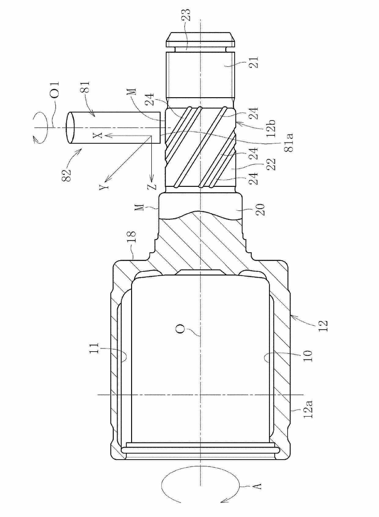
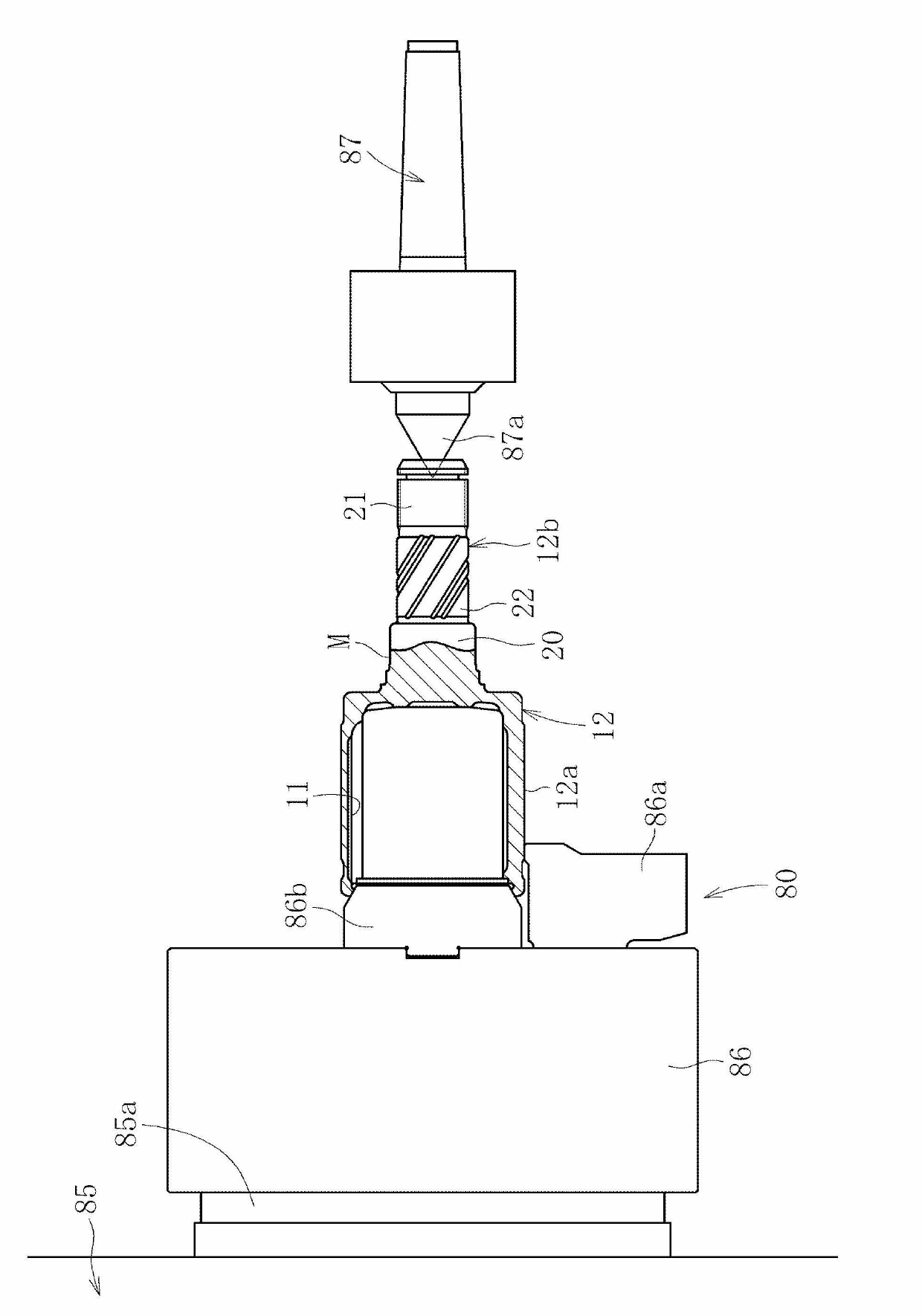
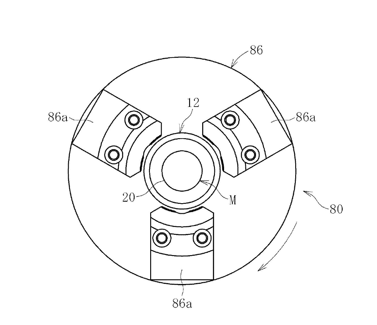
[0026] Below, refer to Figure 1 to Figure 6 Embodiments of the present invention will be described.

[0027] Figure 5 A drive shaft using a constant velocity universal joint processed by the sealing surface processing method according to the present invention is shown. The drive shaft includes an intermediate shaft 1 and constant velocity universal joints 2 and 3 connected to both ends of the intermediate shaft 1 . One constant velocity universal joint 2 is a sliding type constant velocity universal joint, and the other constant velocity universal joint 3 is a fixed type constant velocity universal joint.

[0028] The constant velocity universal joint 2 has: an outer joint member 12, which is formed with raceway grooves 11 extending in the axial direction at equal intervals in the circumferential direction on a cylindrical inner peripheral surface 10; The raceway grooves 14 extending in the axial direction are formed at equal intervals in the circumferential direction on ...


PUM


Abstract

Provided is a method of machining a sealing surface, such that a sealing surface can be finished at low cost and in a short period of time, and such that lead marks can be eliminated and a sealing surface formed with high precision. While a workpiece having sealing surface (M) to be machined is rotated about the axis of the workpiece, the sealing surface (M) is cut and finished with a rotating cutting tool (81). The cutting of the sealing surface (M) by the cutting tool (81) is a type of hardened steel cutting method which generates no lead marks.

Description

technical field [0001] The present invention relates to a method of processing a sealing surface formed on an outer joint member of a constant velocity universal joint used in, for example, a power transmission system of an automobile or various industrial machines. Background technique [0002] The outer joint member of the constant velocity universal joint includes, for example, a mouth and a rod protruding from the bottom wall of the mouth. In addition, an oil seal fitting portion may be provided on the rod portion. The finishing of the outer diameter surface (that is, the sealing surface) of such an oil seal fitting portion uses an elastic grinder as described in Patent Document 1 and the like. [0003] That is, in the technique described in Patent Document 1, first, turning is performed with a turning tool, and then the turning surface is ground with an elastic grindstone to remove turning lead marks. [0004] 【Prior technical literature】 [0005] 【Patent Literature】...

Claims


Application Information

Patent Timeline
IPC IPC(8): B23C3/00F16C19/18F16C33/64F16C33/76F16D3/20F16D3/84
CPCB23C3/04B23C2215/08B23C2222/84B23C2228/24F16D3/227F16D2003/22326F16D2250/00F16D2300/08F16D2300/10F16C33/7826F16C33/583F16C19/186F16C33/64F16C2326/02F16D3/223Y10T409/303752
Inventor 寺田健太郎
Owner NTN CORP
Learn More