
Optical mirror ion beam nano-precision machining method based on combination of material addition and removal

A material addition, optical mirror technology, applied in the field of ion beam polishing, can solve the problems of increased processing time, inability to guarantee, difficult to remove low points of error, etc., to improve surface accuracy and surface roughness, improve surface shape Precision, the effect of maintaining optical surface quality

Active Publication Date: 2012-08-22
NAT UNIV OF DEFENSE TECH
View PDF4 Cites 26 Cited by
  • Summary
  • Abstract
  • Description
  • Claims
  • Application Information

AI Technical Summary

Problems solved by technology

It is difficult to remove the low point of error in the processing of nanometer precision, and it is difficult to realize the removal processing of large error gradient
In order to solve this problem, it usually needs to be combined with other processing techniques, but it cannot guarantee the surface shape accuracy of other areas while removing large gradient errors, and the required processing time will be greatly increased
[0008] Therefore, the ion beam polishing method based on the removal of a single error high point has been difficult to achieve the consistent convergence of the full-frequency surface shape error and the removal of large gradient errors. At present, there is no effective solution to the above-mentioned high-precision optical mirror processing. The processing technology of the problem

Method used

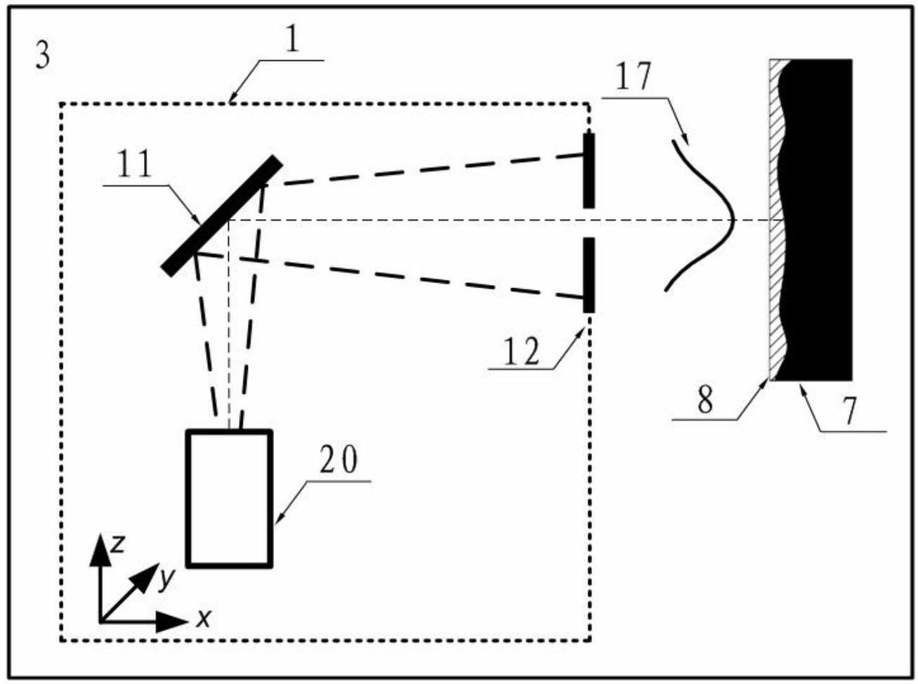
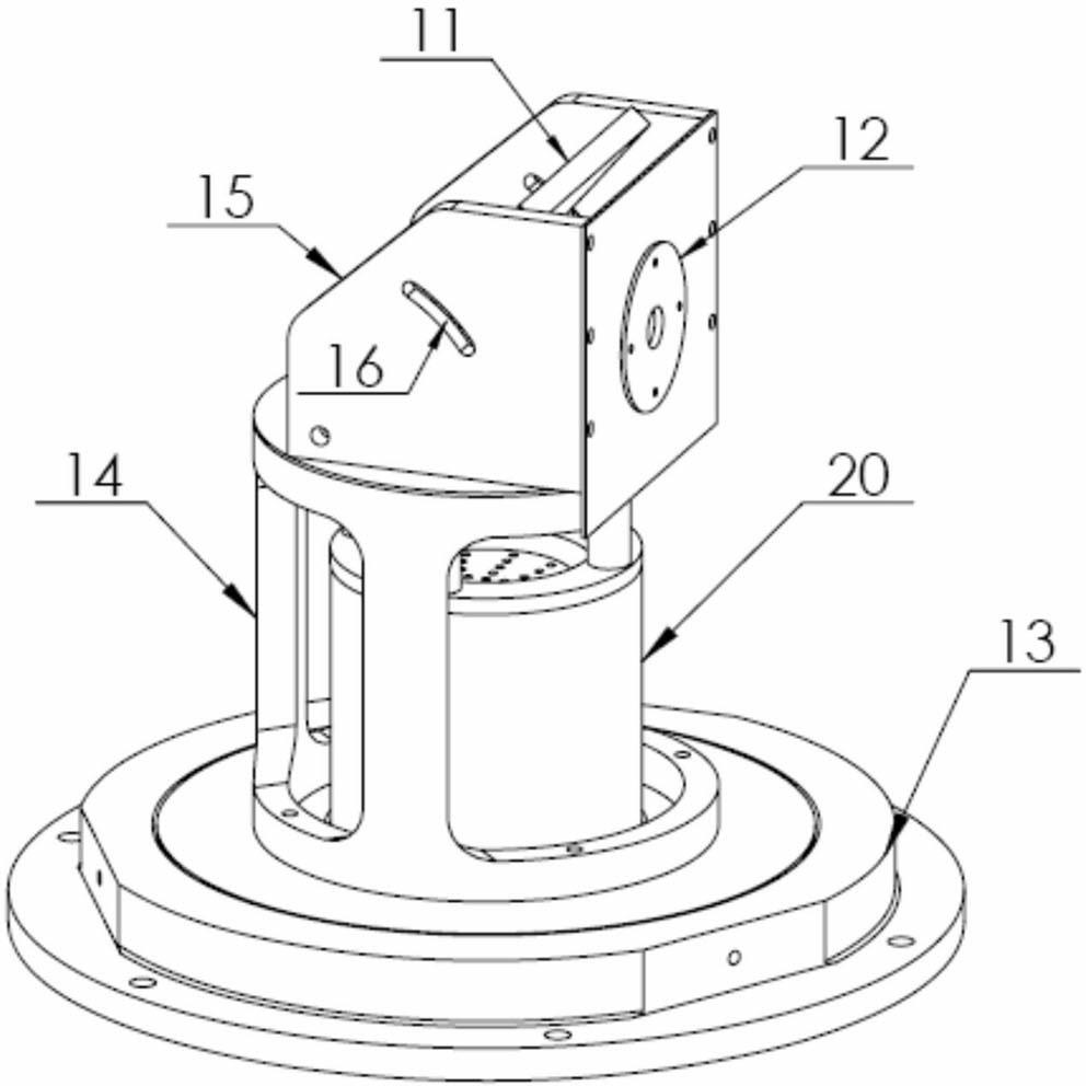
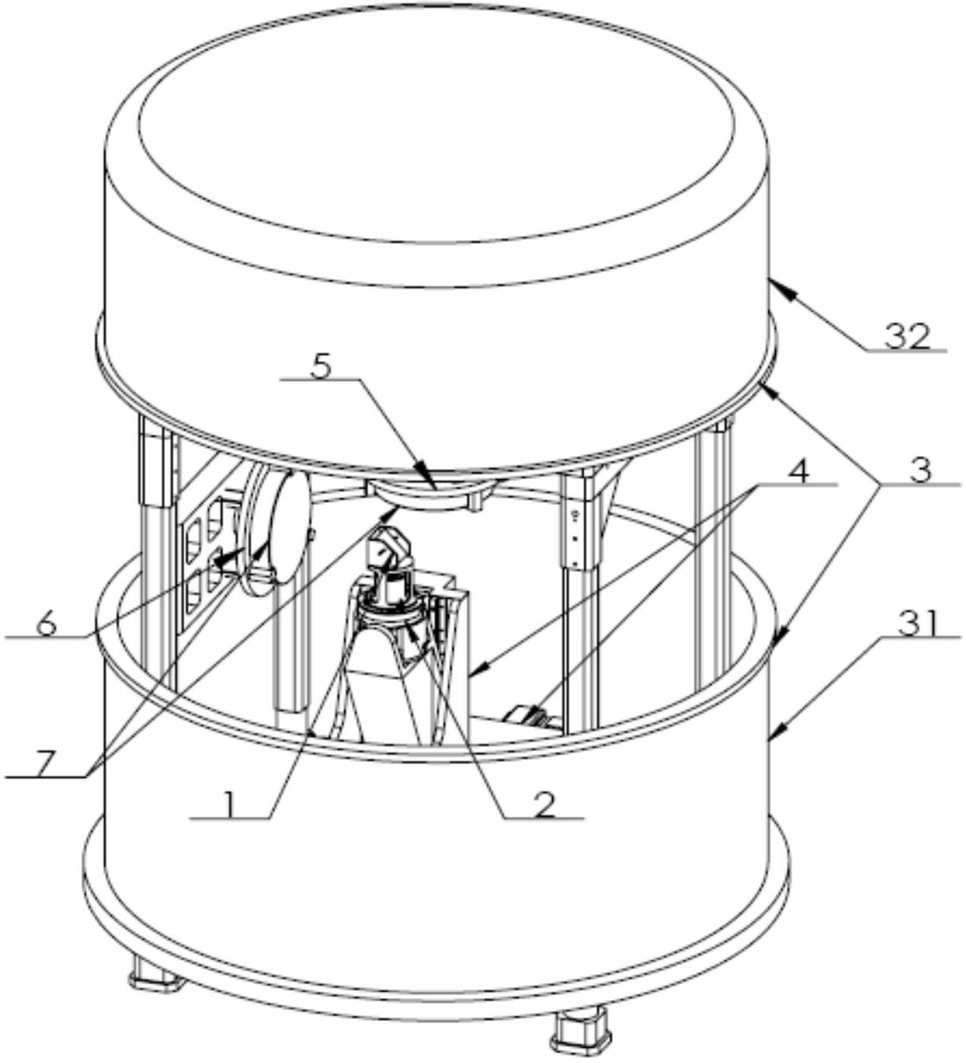

Image

  • Optical mirror ion beam nano-precision machining method based on combination of material addition and removal
  • Optical mirror ion beam nano-precision machining method based on combination of material addition and removal
  • Optical mirror ion beam nano-precision machining method based on combination of material addition and removal

Examples


Embodiment

[0047] An ion beam nanometer-precision machining method based on the combination of material addition and removal according to the present invention. In this embodiment, the workpiece to be processed is a Φ100mm quartz plane (effective aperture is Φ90mm), and the initial surface shape error RMS value of the mirror surface is 110.2nm PV, 23.0nm RMS (see Figure 9 ), the process specifically includes the following steps.

[0048] (1) Obtain the additive function: take an experimental sample of the same material as the workpiece to be processed, and use the wave surface interferometer to measure the initial surface shape error distribution of the experimental sample as follows: Figure 4 As shown; the material addition time is set to 5min, and the ion beam polishing system equipped with an ion beam deterministic addition device is used to add material to a given point of the experimental sample; Measurements are carried out, and the measurement results are as Figure 5 Shown; t...


PUM


Abstract

The invention discloses an optical mirror ion beam nano-precision machining method based on combination of material addition and removal, and the method comprises the following steps: firstly obtaining an addition function, then measuring the surface shape error of a workpiece to be machined, and determining addition residence time according to a two-dimensional convolution formula by taking a numerical value obtained by inversing a measuring result as the additive amount of materials; according to the addition residence time, using an ion beam polishing system to perform deterministic addition control on the workpiece to be machined so as to form a protective sacrificial layer; measuring the surface shape error of the workpiece to be machined again, and then determining removal residence time according to the two-dimensional convolution formula by taking the measuring result as the removal amount of the materials; and using the ion beam polishing system to perform deterministic removal control on the workpiece until removing the protective sacrificial layer so as to complete optical mirror nano-precision machining for the workpiece to be machined. The optical mirror ion beam nano-precision machining method has the advantages of simple processing steps, less investment in equipment and high machining efficiency, and can be used for effectively improving the surface roughness of an optical element, correcting the medium-high frequency error, and the like.

Description

technical field [0001] The invention belongs to the technical field of ion beam polishing processing of optical elements, and in particular relates to an ion beam nano-precision processing method for an optical mirror surface. Background technique [0002] With the continuous improvement of optical system performance, the precision requirements of optical components are getting higher and higher, which poses new challenges to modern optical manufacturing technology. Taking extreme ultraviolet lithography (EUVL) technology as an example, the error mechanisms of different frequency bands of mirrors constituting the extreme ultraviolet lithography (EUVL) system have different influence mechanisms on imaging quality, and the root mean square value of the full frequency band error is required to be controlled in the sub-nanometer range , put forward the most stringent requirements for modern optical manufacturing technology. [0003] A breakthrough in the processing of modern op...

Claims


Application Information

Patent Timeline
Patent Type & Authority Applications(China)
IPC IPC(8): B24B1/00
Inventor 戴一帆廖文林解旭辉周林袁征任虹宇
Owner NAT UNIV OF DEFENSE TECH
Learn More