Cross flow wind wheel and air treatment device with same

A technology of air treatment device and cross-flow wind wheel, which is applied to parts of pumping devices for elastic fluids, liquid fuel engines, mechanical equipment, etc., and can solve the problem of not having tiny adsorption and dust removal functions, and heavy loads on motors and fans , the filter is easy to block and other problems, and the dust removal efficiency will not decay, the service life is long, and the structure is simple and reasonable.

Active Publication Date: 2012-08-22
GD MIDEA AIR-CONDITIONING EQUIP CO LTD
View PDF9 Cites 3 Cited by
  • Summary
  • Abstract
  • Description
  • Claims
  • Application Information

AI Technical Summary

Problems solved by technology

The filtration efficiency of the filter screen in the filter device of this structure decreases significantly with the increase of the use time; in addition, the filter screen is easy to block and needs to be replaced frequently; due to the large thickness and large resistance of the filter screen, the pressure drop after the air passes through the filter Generally, it is more than 50-100 Pa, which leads to the disadvantages of heavy load on the motor and fan equipment in the purification device used with the filter, large motor power, high power consumption and high noise.
[0004] In addition, the traditional cross-flow wind wheel only has the characteristics of pressurized air supply, and does not have the function of micro adsorption and dust removal

Method used


Image

  • Cross flow wind wheel and air treatment device with same
  • Cross flow wind wheel and air treatment device with same
  • Cross flow wind wheel and air treatment device with same

Examples


no. 1 example

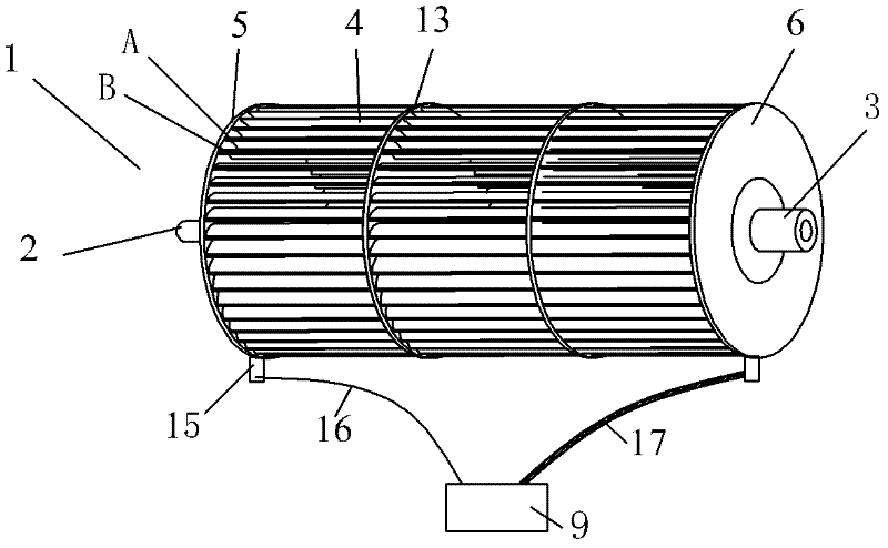
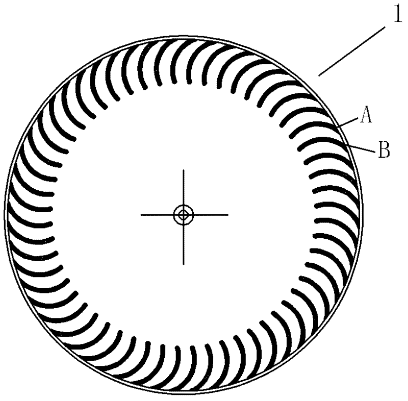
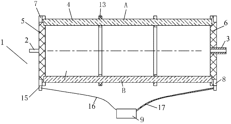
[0045] see Figure 1-Figure 3 , the cross-flow wind wheel 1 includes a shaft 2, a shaft sleeve 3 and blades 4, the blades 4 are arranged in a ring shape at intervals along the circumferential direction, the two ends of the blade 4 are provided with a left end plate 5 and a right end plate 6 for fixing it, the shaft 2 and the The axle sleeve 3 is respectively arranged on the left and right end plates, and the middle part of the blade 4 is also provided with more than one intermediate partition 13 that can strengthen its rigidity. There are two intermediate partitions 13 in this embodiment, and its blade 4 includes several groups that can The conductive first blade A and the second blade B are connected to the high-voltage power supply 9. The potentials of the two groups of blades are different, and they are staggered and non-conductive. A high voltage that can absorb tiny particles in the airflow flowing through the two groups of blades is formed between the two groups of blades. ...

no. 2 example

[0058] see Figure 4 The main difference between this embodiment and the first embodiment is that a second conductive ring 8 is provided on the outer circumference of the right end plate 6 , and a first conductive ring 7 is provided on the inner circumference of the right end plate 6 . Since the first conductive ring 7 and the second conductive ring 8 are arranged on the same right end plate 6 , the first conductive ring 7 and the second conductive ring 8 are separated by an insulating layer. That is to say, in addition to the first conductive ring 7 and the second conductive ring 8, other areas of the right end plate 6, the middle partition 13 and the left end plate 5 are all made of insulating materials, so as to ensure that the first blade A and the second blade A Blades B are insulated from each other.

[0059] For clarity, the high-voltage power supply and connecting wires are not shown in the figure. Other unmentioned parts are the same as the first embodiment and will...

no. 3 example

[0061] see Figure 5 The main difference between this embodiment and the first embodiment is that a second conductive ring 8 is provided on the outer circumference of the left end plate 7 , and a first conductive ring 7 is provided on the inner circumference of the left end plate 5 . Since the first conductive ring 7 and the second conductive ring 8 are disposed on the same left end plate 7 , the first conductive ring 7 and the second conductive ring 8 are separated by an insulating layer. That is to say, in addition to the first conductive ring 7 and the second conductive ring 8, other areas of the left end plate 5, the middle partition 13 and the right end plate 6 are all made of insulating materials to ensure that the first blade A and the second blade A Blades B are insulated from each other.

[0062] For clarity, the high-voltage power supply and connecting wires are not shown in the figure. Other unmentioned parts are the same as the first embodiment and will not be re...


PUM

PropertyMeasurementUnit
diameteraaaaaaaaaa
thicknessaaaaaaaaaa
thicknessaaaaaaaaaa

Abstract

The invention relates to a cross flow wind wheel which comprises shafts, shaft sleeves and blades; the blades are arranged to be a circular shape at intervals along a circumferential direction; both ends of the blades are provided with left end plates and right end plates for fixing the blades; the shafts and the shaft sleeves are respectively arranged on the left end plates and the right end plates; the middle parts of the blades are provided with more than one middle division board capable of reinforcing the rigidity of the blades; the blades comprise a plurality of groups of first blades and second blades, which can be connected with high-voltage power supplies and are conductive; the potentials of the two groups of blades are different, and the two groups of blades are mutually staggered and are not communicated; and a high-voltage dust removal channel which can absorb micro particles which flow through the airflow in the channel is formed between the two groups of blades. An air treatment device with the cross flow wind wheel comprises a shell body which consists of a volute casing and a volute tongue and the cross flow wind wheel; the cross flow wind wheel is connected into the shell body through the rotation of a motor; and the air treatment device also comprises a corona discharge device which can enable the micro particles in the airflow to be charged or a negative ion emission ionization device, and is connected with the high-voltage power supply. The invention has the characteristics of simple and reasonable structure, high dust collection efficiency, small resistance, low power consumption, low noise and no pressure loss.

Description

technical field [0001] The invention relates to a cross-flow wind wheel and an air treatment device with the cross-flow wind wheel. Background technique [0002] With the development of industrial production and the increase in the use of automobiles, the dust in the atmosphere has increased, and the air pollution has intensified. With the intensification of outdoor air pollution, the dust in the indoor air has also increased. On the other hand, with the improvement of people's living standards, consumers have put forward strict requirements for the purification of indoor air. Relevant national departments have also strengthened the detection of tiny particles of PM2.5. [0003] At present, the traditional air purification device mainly passes through a dense black handkerchief HEPA filter with a thickness greater than 30 mm. When passing through the dense filter, the tiny particles in the air flow are blocked by the filter and thus absorbed. For example, Chinese Patent Do...

Claims


Application Information

Patent Timeline
Patent Type & Authority Applications(China)
IPC IPC(8): F04D29/26F04D29/02A61L9/22
Inventor 游斌吕艳红
Owner GD MIDEA AIR-CONDITIONING EQUIP CO LTD
Why Eureka
Try Eureka