Perimeter security system based on single optical fiber and fiber bragg grating of single optical fiber

A security system, single-fiber technology, used in anti-theft alarms, optical device exploration, instruments, etc., can solve the problems of complex signal demodulation, increased fiber loss, failure to accurately locate, etc., to achieve low energy dependence, high environmental Tolerance, simple structure effect

Inactive Publication Date: 2012-08-22
BEIJING JIAOTONG UNIV
View PDF12 Cites 12 Cited by
  • Summary
  • Abstract
  • Description
  • Claims
  • Application Information

AI Technical Summary

Problems solved by technology

The optical power loss method is to identify the interference signal by real-time monitoring of the optical power change at the receiving end of the optical fiber under test. This method has low precision and cannot be accurately located; The principle of reflection, accepting backscattered light, using the relationship between distance and time to detect the position of fiber disturbance, this method measures the signal is very weak, not suitable for dynamic detection, and its cost is high; Sagnac interference field method is to use The two optical fibers in the optical cable form a Sagnac interference field to detect interference signals. This method requires two optical fibers. As the transmission distance increases, the loss of the optical fiber doubles and the accuracy is greatly reduced; the reflection wavelength of the fiber grating is biased. At present, this method is widely used, such as patent 201010147787.6, patent 200810157485.X, patent 200910243040.8, etc. This method needs to accurately measure the change of the reflection wavelength

Method used


Image

  • Perimeter security system based on single optical fiber and fiber bragg grating of single optical fiber
  • Perimeter security system based on single optical fiber and fiber bragg grating of single optical fiber
  • Perimeter security system based on single optical fiber and fiber bragg grating of single optical fiber

Examples


Example Embodiment

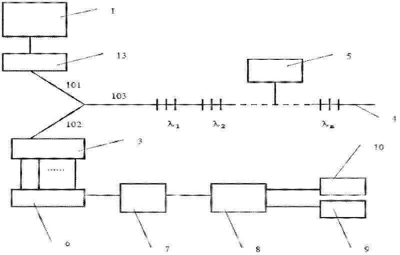
[0018] Embodiment one, see figure 1 , a single optical fiber and single fiber grating cable perimeter security system, the output end of the light source 1 of the system is connected to the input end of the phase modulator 13, and the output end of the phase modulator 13 is connected to the first branch 101 of the Y splitter, Y The second branch 102 of the splitter is connected to the input end of the optical splitter 3, the third branch 103 of the Y splitter is connected to one end of the optical fiber 4, the knock signal 5 is applied to the optical fiber 4, and the output of the splitter 3 is connected to the photodetector 6, the output of the photodetector 6 is connected to the input of the amplifying circuit 7, the output of the amplifying circuit 7 is connected to the input of the signal processing module 8, one output of the signal processing module 8 is connected to the display module 9, and the other output Connect the speaker 10.

[0019] First write the reflection w...

Example Embodiment

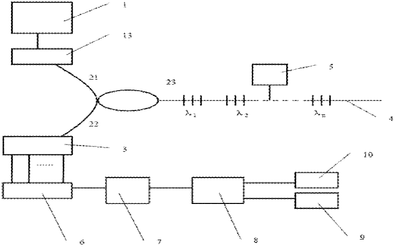
[0021] Embodiment two, see figure 2 , a single optical fiber and single fiber grating optical cable perimeter security system, the output end of the light source 1 of the system is connected to the input end of the phase modulator 13, and the output end of the phase modulator 13 is connected to the first port 21 of the three-port coupler, The second port 22 of the three-port coupler is connected to the input end of the optical splitter 3, and the third port 23 of the three-port coupler is connected to one end of the optical fiber 4, and the knocking signal 5 is applied to the optical fiber 4, and the output of the splitter 3 The terminal is connected to the input end of the photodetector 6, the output of the photodetector 6 is connected to the input end of the amplifying circuit 7, the output of the amplifying circuit 7 is connected to the input end of the signal processing module 8, and an output terminal of the signal processing module 8 is connected to the display module 9 ...

Example Embodiment

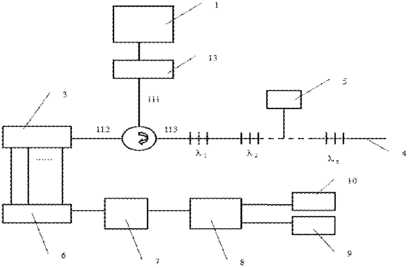
[0024] Embodiment three, see image 3 , a single fiber and single fiber grating cable perimeter security system, the output end of the system multi-wavelength light source 1 is connected to the input end of the phase modulator 13, and the output end of the phase modulator 13 is connected to the first port of the three-port circulator 111, the second port 112 of the three-port circulator is connected to the input end of the wave splitter 3, the third port 113 of the three-port circulator is connected to one end of the optical fiber 4, and the knocking signal 5 is applied to the optical fiber 4, and the wave splitter 3 The output terminal is connected to the input terminal of the photodetector 6, the output of the photodetector 6 is connected to the input terminal of the amplifier circuit 7, the output of the amplifier circuit 7 is connected to the input terminal of the signal processing module 8, and an output terminal of the signal processing module 8 is connected to the displa...


PUM


Abstract

The invention discloses a perimeter security system based on a single optical fiber and a fiber bragg grating of the single optical fiber, which is suitable for fields such as optical fiber communication and optical fiber sensing. An output end of a light source (1) of the system is connected with an input end of a phase modulator (13); an output end of the phase modulator is connected with a first branch (101) of a Y branching device; a second branch (102) of the Y branching device is connected with an input end of a wave separator (3); a third branch (103) of the Y branching device is connected with one end of an optical fiber (4); a knocking signal (5) is applied to the optical fiber and an output end of the wave separator (3) is connected with an input end of a photoelectric detector (6); an output end of the photoelectric detector is connected with an input end of an amplifying circuit (7); an output end of the amplifying circuit is connected with an input end of a signal processing module (8); and an output end of the signal processing module is connected with a display module (9) and a loudspeaker (10). The system has a simple structure and is easy to realize; and an interference field can be formed by the single optical fiber to detect and position an invading signal.

Description

technical field [0001] The invention relates to a perimeter security system for a single optical fiber and a single optical fiber grating optical cable, and is suitable for the fields of optical fiber sensing, optical fiber communication and the like. Background technique [0002] Modern perimeter security systems are applied to areas with high confidentiality requirements or large-scale perimeter security requirements such as military sites, banks, museums, and airports. It has important practical significance for timely detection and location of intrusion behaviors. [0003] At present, the perimeter security systems based on optical fibers mainly include the following methods: optical power loss method, optical time domain reflection method, Sagnac interference field method, and fiber Bragg grating reflection wavelength shift method. The optical power loss method is to identify the interference signal by real-time monitoring of the optical power change at the receiving en...

Claims


Application Information

Patent Timeline
IPC IPC(8): G08B13/186G01V8/10
Inventor 宁吉粤李超裴丽
Owner BEIJING JIAOTONG UNIV
Why Eureka
Try Eureka