Rotor of resultant magnetic field

A technology for synthesizing magnetic fields and rotors, applied in the fields of machinery manufacturing and motors, can solve the problems of increasing the magnetic pole magnetic density of the motor and the utilization rate of magnetic materials is not improved, and achieve the effects of improving the magnetic density, small rotor diameter, and high cylindricity

Inactive Publication Date: 2012-08-22
HANGZHOU ZHONGJUN AUTOMOBILE
View PDF7 Cites 6 Cited by
  • Summary
  • Abstract
  • Description
  • Claims
  • Application Information

AI Technical Summary

Problems solved by technology

The magnetic field is composed of the magnetic steel in the commutation area and the magnetic steel of the magnetic pole centerline. The magnetic pole flux density of the motor is greatly increased. However, the method of increasing the magnetic flux density is only to add a pair of magnetic steel in the center of the magnetic pole. Compared with ordinary motors, it still needs to use arc Surface structure of the magnetic tile, the utilization rate of the magnetic material has not improved

Method used


Image

  • Rotor of resultant magnetic field
  • Rotor of resultant magnetic field
  • Rotor of resultant magnetic field

Examples


Embodiment 1

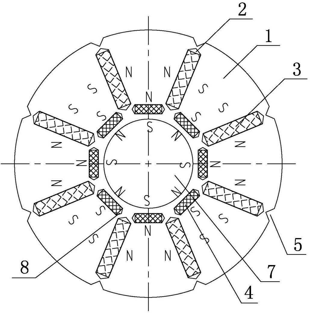
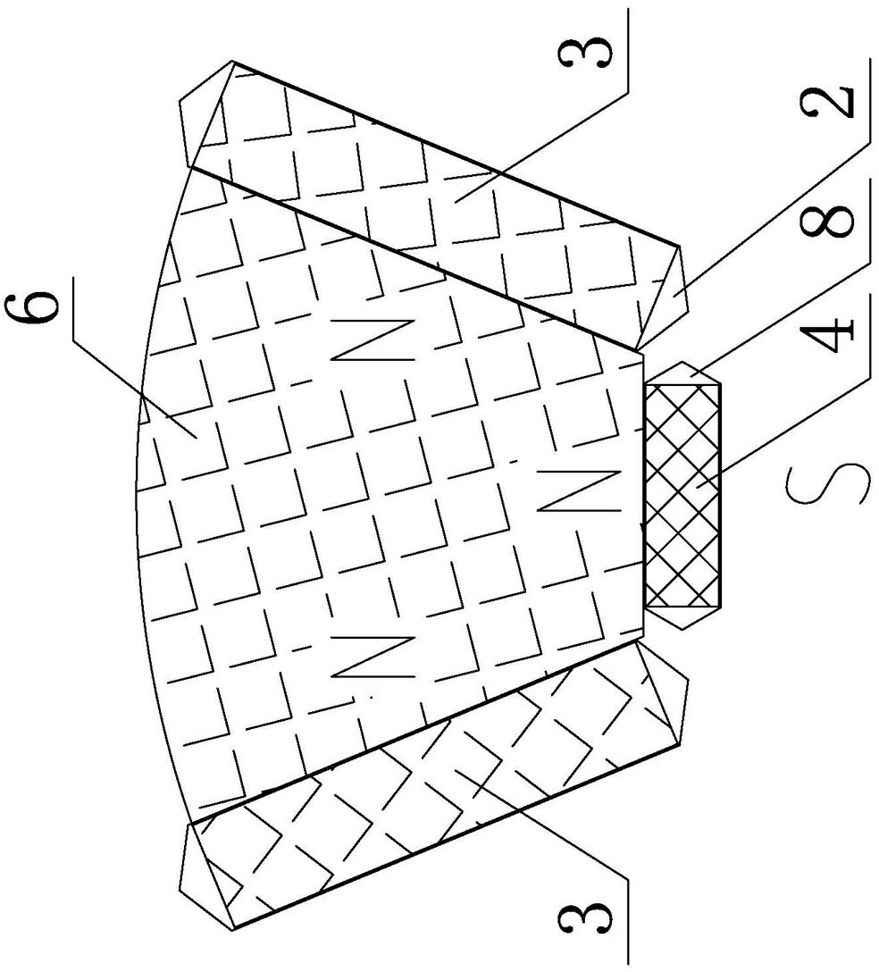
[0023] Embodiment 1: as Figure 1-Figure 4 As shown, this embodiment includes a coaxially arranged rotor core 1 (silicon steel sheet) and a rotor shaft 7, wherein the rotor core 1 is evenly punched with eight main magnetic steel mounting holes 2 in the radial direction, and the holes are embedded with There are main magnets 3 with a rectangular cross-section. After installation, each main magnet 3 is in the shape of a spoke with the axis of the rotor shaft 7 as the center, and is arranged radially opposite each other, that is, each main magnet 3 is arranged along the rotor core 1 diameter Arranged evenly in the direction; A secondary magnetic steel mounting hole 8 is punched between two adjacent main magnetic steel mounting holes 2, close to the inner diameter of the rotor core 1, and a secondary magnetic steel 4 with a rectangular cross section is embedded in the hole. In order to reduce magnetic flux leakage; after the installation is completed, each auxiliary magnet 4 is ar...

Embodiment 2

[0027] Embodiment 2: as Figure 5-Figure 7 As shown, the structure of this embodiment is basically the same as that of Embodiment 1, the difference is that the secondary magnetic steel installation hole 8 and the secondary magnetic steel 4 are removed, and at the same time, there are punched on the rotor core 1 between two adjacent main magnetic steels 3 The slots 9 with an isosceles triangle cross section, that is, the slots 9 are evenly arranged radially along the rotor core 1, and their length is roughly the same as that of the main magnetic steel 3, and the bottom of the slots is close to the rotor core 1 Inner diameter, and parallel to the tangent arrangement of the circumferential surface of the rotor shaft 7, the symmetry axes of the two adjacent main magnets 3 located on both sides of the slot coincide with the angle bisector of the top angle of the slot; the two adjacent main magnets 3 and a slot 9 located therebetween form two fan ring areas, and the iron cores in th...


PUM


Abstract

The invention relates to a rotor of a resultant magnetic field, which is simple in structure, small in volume, convenient to process, high in magnetic energy level and magnetic shoe utilization rate and capable of greatly reducing usage quantity of magnets and silicon sheets and production cost under same efficiency and power levels. The technical scheme is that the rotor of the resultant magnetic field comprises a rotor core and a rotor spindle which are arranged coaxially. The rotor is characterized in that main magnetic steels in even numbers are arranged evenly on the rotor core along a radial direction, the opposite faces of two adjacent main magnetic steels are both North poles or South poles, a magnet sealing device which is used for reducing magnet leakage is arranged between two adjacent main magnetic steels, and the magnet sealing device is arranged symmetrically, and an symmetry axis of two adjacent main magnetic steels serves as a reference axis. The rotor of the resultant magnetic field is applicable to the field of electrical motors or mechanical manufacture and the application classification belongs to electrically driven vehicle driving and industrial application technologies.

Description

technical field [0001] The invention relates to a rotor for synthesizing a magnetic field, in particular to a rotor for synthesizing a magnetic field for a brushless DC motor, which is mainly applicable to the fields of motor and machinery manufacturing, and belongs to electric vehicle driving and industrial application technology in application classification. Background technique [0002] At present, the rotors of inner-rotor brushless DC motors on the market all adopt a structure in which magnetic tiles are pasted on the outer edge of the iron core. This type of arc-shaped magnetic tile needs to be cut by wire before grinding the arc surface, the utilization rate of the magnetic material is low, and the processing technology is complicated; at the same time, due to the high-speed rotation of the rotor, a stainless steel sleeve is generally required to prevent the magnetic tile from being subjected to centrifugal force. Dislocation not only complicates the assembly process...

Claims


Application Information

Patent Timeline
Patent Type & Authority Applications(China)
IPC IPC(8): H02K1/27H02K1/28
CPCY02T10/641Y02T10/64
Inventor 陈波邬海根徐彬李航
Owner HANGZHOU ZHONGJUN AUTOMOBILE
Why Eureka
Try Eureka