Device and process for regenerating active carbon

A regeneration device and activated carbon technology, which is applied in filter regeneration, petroleum industry, filtration and separation, etc., can solve the problems of low regeneration efficiency and a small amount of activated carbon for one-time regeneration, and achieve the effect of large regeneration amount, simple production device and high-efficiency regeneration.

Active Publication Date: 2012-09-05
NANJING UNIV OF TECH
View PDF4 Cites 15 Cited by
  • Summary
  • Abstract
  • Description
  • Claims
  • Application Information

AI Technical Summary

Problems solved by technology

[0004] The purpose of the present invention is to improve the existing activated carbon device single-use electrochemical method regeneration efficiency is low and the problem of one-time regenerated activated carbon is small and the present invention proposes a kind of activated carbon regeneration device, another object of the present invention is to provide a kind of utilization The technology of above-mentioned device regenerating activated carbon

Method used


Image

  • Device and process for regenerating active carbon
  • Device and process for regenerating active carbon
  • Device and process for regenerating active carbon

Examples


Embodiment 1

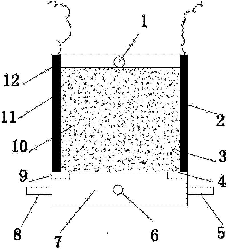
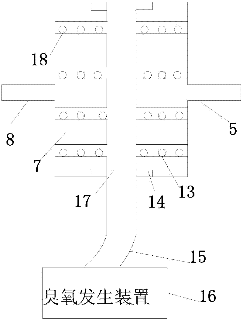
[0018] Such as figure 1 As shown: plexiglass is used as the material of the shell and the hydraulic distribution plate. The shell is a cuboid, and the hydraulic distribution plate is placed on the baffle tightly bonded to the inner wall of the device. The hydraulic distribution plate divides the device into the reaction chamber and the exposure chamber. In the gas chamber, graphite electrodes are respectively set on the side walls of the relative position of the reaction chamber as anode and cathode. The anode and cathode are connected to the power supply through wires. The air inlet is connected to the ozone generator, the aeration pipes are arranged in the shape of "Feng", and the branch pipes of the aeration pipes are uniformly opened with round holes as aeration holes, and each of them is opened at the relative position of the side wall parallel to the main pipe of the aeration hole. The circular hole acts as an inlet for contaminated water and electrolyte.

Embodiment 2

[0020] The structure of the device is as in Example 1, wherein the ratio of the reaction chamber to the aeration chamber is 3:1, the thickness of the electrode is 10mm, the aperture of the aeration inlet is 8mm, the aperture of the aeration hole is 2mm, and the aperture of the electrolyte inlet is 10mm , put 400g of activated carbon into the reaction chamber, pump 500mg / L of phenol solution into the reaction chamber through the polluted water inlet at a speed of 8ml / min, measure the concentration of phenol when the water is discharged, and stop pumping after 2L of polluted water is processed, Close the polluted water inlet and open the regeneration solution inlet, pump the NaCl electrolyte (concentration: 3g / L) into the reaction chamber at a rate of 8ml / min, when the electrolyte just covers the activated carbon layer, turn on the power and adjust the current to 0.1A , turn on the ozone generator for regeneration, adjust the intake flow to 0.3L / min, the electrolyte flows out fro...

Embodiment 3

[0022] The structure is as in Example 1, the ratio of the reaction chamber and the aeration chamber is 4:1, the thickness of the electrode is 10mm, the aperture of the aeration inlet is 8mm, the aperture of the aeration hole is 2mm, the aperture of the electrolyte inlet is 10mm, and 500g Put the activated carbon into the reaction chamber, pump 2000mg / L phenol solution into the reaction chamber through the polluted water inlet at a rate of 5ml / min, measure the concentration of phenol when the water is discharged, stop pumping and close the polluted water after 2L of polluted water is treated Open the regeneration solution inlet at the inlet, pump the NaCl electrolyte (with a concentration of 5g / L at a rate of 25ml / min) into the reaction chamber, when the electrolyte just covers the activated carbon layer, turn on the power, adjust the current to 0.3A and turn on the ozone generator For regeneration, adjust the air intake flow rate to 0.6L / min, and the electrolyte flows out from ...


PUM


Abstract

The invention relates to a device and a process for regenerating active carbon. The device comprises a reaction chamber and an aeration chamber, wherein the aeration chamber is arranged at the bottom of the reaction chamber; the reaction chamber and the aeration chamber are separated from each other by a water distribution plate; an external power source is arranged outside the reaction chamber, and connected to an anode and a cathode both mounted inside the device; the anode and the cathode are mounted on the two sides of the reaction chamber; an electrolyte inlet, a polluted water inlet and an aeration inlet are formed on the bottom of the aeration chamber; an aeration pipe is arranged in the aeration chamber, and connected to an ozone generating device through a gas pipe; and an electrolyte is filled in the aeration chamber via the electrolyte inlet, flows through the reaction chamber and then flows out via a water outlet formed at the top of the reaction chamber. Compared with the prior art, a method of combining an electrochemical process with ozone for regeneration is adopted in the invention, so that the regeneration efficiency of the active carbon is improved, and the device is relatively simple.

Description

technical field [0001] The invention relates to an activated carbon regeneration device and process, belonging to the technical field of special equipment for chemical production. Background technique [0002] As an excellent adsorbent, activated carbon has a well-developed pore structure, a large specific surface area, and excellent adsorption performance. In the early 1960s, European and American countries began to use activated carbon adsorption to treat urban drinking water and industrial wastewater. Activated carbon has developed rapidly in the treatment of industrial wastewater, both in terms of technology, application range and treatment scale, such as papermaking wastewater, electroplating wastewater, oil refining wastewater and explosives wastewater treatment. Satisfactory results have been obtained. If the used activated carbon is not recycled, it will cause secondary pollution to the environment. Therefore, from the perspective of economy and environmental prote...

Claims


Application Information

Patent Timeline
Patent Type & Authority Applications(China)
IPC IPC(8): B01J20/34B01J20/20
Inventor 徐炎华赵贤广王欣欣赵浩
Owner NANJING UNIV OF TECH
Why Eureka
Try Eureka