
Middle and low temperature control device of simulated moving bed chromatograph

A technology for simulating moving bed and temperature control device, which is applied in the direction of temperature control, measuring device, and material separation by using electric methods, which can solve the problems of no better solution, complicated design, difficult operation, etc., and solve the problem of temperature balance , Improve production efficiency and consume less energy

Inactive Publication Date: 2012-09-05
UNIV OF SCI & TECH LIAONING
View PDF7 Cites 1 Cited by
  • Summary
  • Abstract
  • Description
  • Claims
  • Application Information

AI Technical Summary

Problems solved by technology

[0004] The traditional temperature constant temperature control system often uses heating wire heating or water circulation heating method combined with the temperature control system to control the temperature in a certain space, often resulting in uneven temperature in the constant temperature box, which is inconvenient for temperature detection
At the same time, in a high temperature environment, how to maintain the low temperature state of the separation system of the simulated moving bed device, there is still no good solution.
A Chinese patent applied by Japan Tosoh Co., Ltd., publication number: CN101622535A, the application provides a column thermostat capable of maintaining extremely high temperature stability, which can only provide a stable temperature for one chromatographic column, and cannot maintain eight Simultaneous temperature control of even more chromatographic columns; at the same time, the patent design is complex and the operation is difficult
[0005] After reviewing the existing public information, no similar reports have been found on the temperature control system applied to the separation space of the simulated moving bed

Method used


Image

  • Middle and low temperature control device of simulated moving bed chromatograph
  • Middle and low temperature control device of simulated moving bed chromatograph
  • Middle and low temperature control device of simulated moving bed chromatograph

Examples


Embodiment Construction

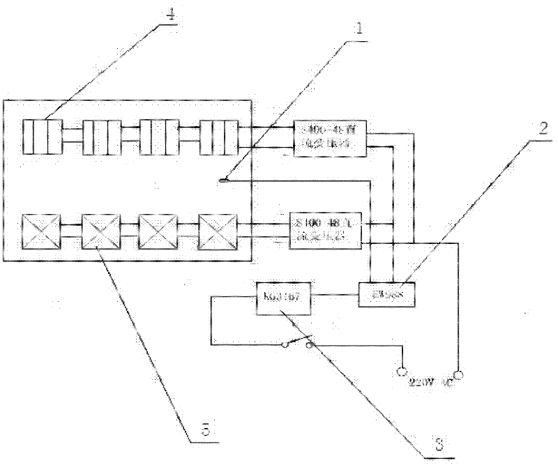
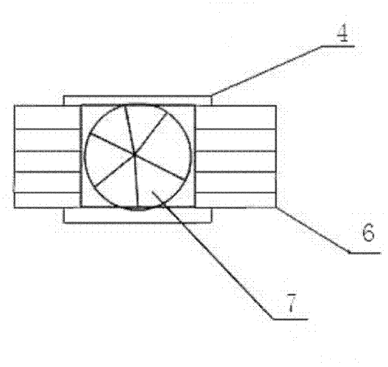
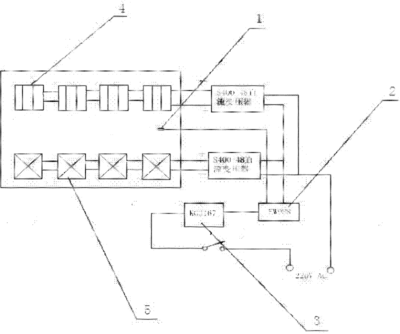
[0017] Such as figure 1 and figure 2 As shown, the medium and low temperature temperature control device of the simulated moving bed chromatography is composed of a temperature control box, a temperature adjustment component, a temperature sensor 1, a temperature controller 2, a temperature reservation setting module 3 and a power supply system. Wherein the temperature regulating part is composed of a semiconductor heating sheet 4, a semiconductor cooling sheet 5, an aluminum alloy heat sink 6 and a fan 7. The semiconductor heating sheet 4 is installed inside the temperature control box, and the installation method is in series, and the heat sink is installed on the surface of each semiconductor heating sheet and semiconductor cooling sheet. The temperature controller is installed inside the temperature control box, and the temperature controller is connected to the temperature sensor, the semiconductor heating sheet and the semiconductor cooling sheet through wires to reali...


PUM


Abstract

The invention discloses a middle and low temperature control device of simulated moving bed chromatograph which can carry out good temperature control over simulated moving bed separated space. The device comprises a temperature control box body, a temperature adjusting part, a temperature sensor, a temperature controller, a temperature presetting module and a power supply system. The device can maintain constant temperature of simulated moving bed separated space and realize high-precision and low-energy-consumption middle and low temperature control with the temperature control range between minus 20 DEG C and 40 DEG C. The device can solve the problem of temperature balance of simulated moving bed separated space; in addition, the energy consumption is less; and the temperature presetting module can realize the function of turning on temperature control appointment and the temperature of separating columns of simulated moving bed chromatograph is controlled in advance before operators are on duty, so that the production efficiency is improved.

Description

technical field [0001] The invention relates to a medium and low temperature temperature control device for simulated moving bed chromatography. Background technique [0002] Simulated moving bed chromatographic separation technology is a new type of high-efficiency fine separation technology based on chromatographic separation and combined with simulated moving bed technology. The technology relies on a simulated moving bed chromatographic separation unit for its separation capabilities. In order to ensure the stability of chromatographic separation, it is necessary to control the temperature of the separation column during the chromatographic separation process. The chromatographic column temperature, which is highly dependent on the adsorption and desorption process of the stationary phase packed in the separation column, is efficiently controlled in order to achieve component separation and obtain high reproducibility. The simulated moving bed temperature control devic...

Claims


Application Information

Patent Timeline
Patent Type & Authority Applications(China)
IPC IPC(8): G01N30/30G01N30/46G01N30/38B01D15/16B01D15/18G05D23/19
Inventor 张伟王绍艳李芊丛景香唐晓丹
Owner UNIV OF SCI & TECH LIAONING
Learn More