
Eureka
For R&D, Eureka makes reading and utilizing patents & technical documents easy.
Eureka AIR
Designed for self-driven R&D workflows. Generate viable solutions, solve complex R&D challenges, empower your innovation with AI.

Eureka Materials
Designed for material experts only. Revolutionize your material R&D, from search, analyze, to developing new materials.

TechResearch
Generate reliable direction feasibility study reports for your R&D in just a few steps.

TechSeek
Discover and master advanced knowledge NOW. Basics, ideas, possibilities, all at once.

TechMind
As an expert in R&D Theories, TechMind can generates customized viable solutions instantly.

TechRisk
Analyze your overall solution with one click, know your potential R&D risks in advance.

TechMonitor
Get weekly tech updates, stay abreast of the latest tech innovations and key insights.
Very-high frequency (VHF) broadband transceiving antenna used on mobile carrier
A technology for transmitting and receiving antennas and mobile carriers, which is applied in directions such as antennas and radiating element structures suitable for movable objects, and can solve problems affecting antenna performance stability, magnetic loop or network loss, and antenna efficiency reduction.
- Summary
- Abstract
- Description
- Claims
- Application Information
AI Technical Summary
Problems solved by technology
Method used
Image

Examples
Embodiment 1
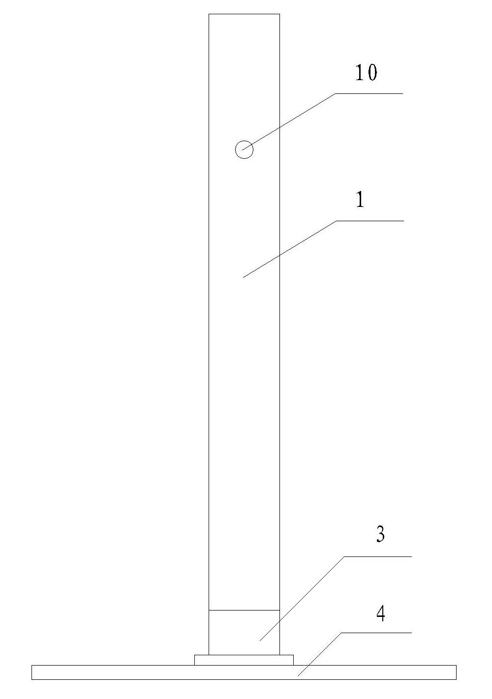
[0019] A VHF transceiver vehicle-mounted antenna includes a radiator 1, a feeder cable 2, and an automatic antenna tuner 3 arranged at the bottom of the antenna and connected to the feeder cable 2.
[0020] Such as figure 1 As shown, the radiator 1 is a cylindrical body with a diameter of 70 mm and a length of 650 mm; the radiator 1 is arranged in a glass fiber reinforced plastic cover. In addition, the feeding point 10 is 235 mm away from the top of the radiator 1 .
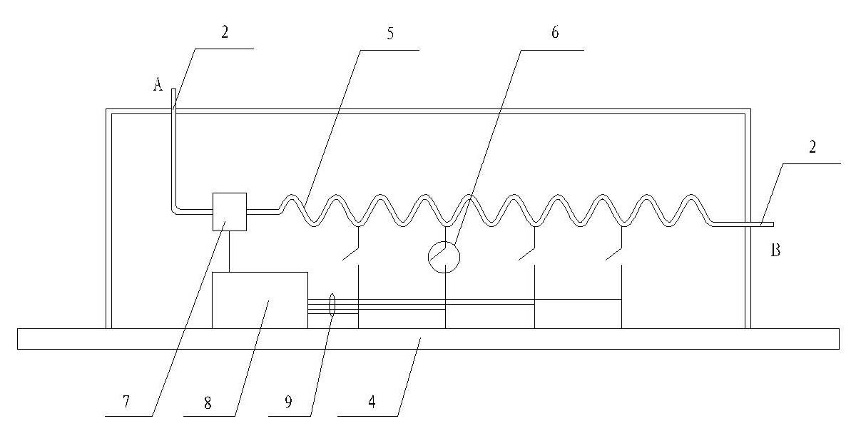
[0021] The automatic antenna tuner 3 is composed of an antenna impedance testing module 7 , a tuning inductance 5 and an inductance automatic tuning control circuit module 8 . These three modules all use commercially available products, preferably the antenna impedance test module (article number: XW035422), tuning inductor (article number: XW064792) and inductance automatic tuning control circuit module (article number: XW021544) produced and sold by Xi’an Xingwang Antenna Technology Co., Ltd. ).
Embodiment 2
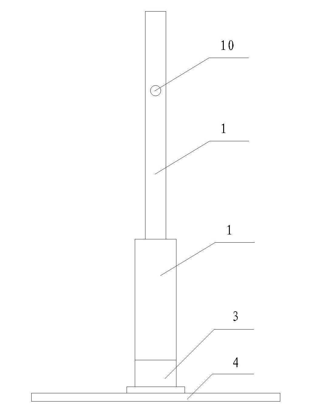
[0024] A military VHF transceiver antenna includes a radiator 1, a feeder cable 2, and an automatic antenna tuner 3 arranged at the bottom of the antenna and connected to the feeder cable 2. A standard military anti-collision spring base is additionally installed between the radiator 1 of the antenna and the automatic antenna tuner 3 to slow down the vibration generated by the vehicle during driving.
[0025] The radiator 1 is a cylindrical body with a diameter of 100 mm and a length of 750 mm; the feeding point 10 of the antenna is 250 mm from the top of the radiator 1 .
[0026] Such as figure 2 As shown, the automatic antenna tuner 3 is composed of an antenna impedance test module 7, a tuning inductance 5 and an inductance automatic tuning control circuit module 8, wherein the antenna impedance test module 7 is used to detect the impedance of the antenna in real time, and the inductance automatic tuning control The circuit module 8 controls the tuning inductance 5 in rea...
Embodiment 3
[0030] The structure of the VHF transceiver vehicle-mounted antenna described in this embodiment is basically the same as that of the VHF transceiver vehicle-mounted antenna described in Embodiment 2, the difference is that in the present embodiment, the diameter of the described radiator 1 is 135 millimeters, and the length is 830 millimeters; The radiator 1 is arranged in a glass fiber reinforced plastic cover. In addition, the feeding point 10 is 265 mm away from the top of the radiator 1 .
[0031] The total height of the military VHF transceiver vehicle antenna is 1000 mm, the performance is that the standing wave ratio is less than 2.5 in the whole frequency band, the gain is not less than 3 meters for the middle feed and 1.8 meters for the low feed antenna, and the antenna radiation pattern is omnidirectional in the horizontal plane.
PUM
 Abstract
Description
Claims
Application Information
 - R&D Engineer
- R&D Manager
- IP Professional
- Industry Leading Data Capabilities
- Powerful AI technology
- Patent DNA Extraction
Browse by: Latest US Patents, China's latest patents, Technical Efficacy Thesaurus, Application Domain, Technology Topic, Popular Technical Reports.
© 2024 PatSnap. All rights reserved.Legal|Privacy policy|Modern Slavery Act Transparency Statement|Sitemap|About US| Contact US: help@patsnap.com