Manufacturing method of pedestal bearing for turbocharger and positioning tool for same

A technology of a turbocharger and a manufacturing method, which is applied in the direction of grinding workpiece supports, etc., can solve the problems of scrapped parts, scrapped workpieces, unable to meet the requirements of workpieces, etc., so as to reduce the process of scraping inner holes, improve the qualification rate and production efficiency Effect

Active Publication Date: 2012-09-12
CHONGQING JIANGJIN SHIPBUILDING IND
View PDF8 Cites 20 Cited by
  • Summary
  • Abstract
  • Description
  • Claims
  • Application Information

AI Technical Summary

Problems solved by technology

[0004] Although the turbocharger support bearing can be manufactured according to the above-mentioned manufacturing method, the above-mentioned method of manufacturing the turbocharger support bearing has the following disadvantages: 1. After the rough turning of the workpiece in the process (2) and (3), it is easy to produce machining The processing stress must be eliminated, but the workpiece is stress-relieved in process (1). This only eliminates the workpiece stress, but cannot eliminate the processing stress. For high-precision parts, there are still defects of deformation
[0005] 2. When fine grinding the hole and thrust surface in the process (10), the hard three jaws are used. If the clamping force is too large, the parts will be deformed, and the roundness of the finely ground holes is seriously out of tolerance, causing the parts to be scrapped.
[0009] In the above process, although the soft three jaws can overcome the deformation of the part after clamping the part during the processing, it still has the following shortcomings: 1. In the process (2) and (3), the roughness of the workpiece It is easy to produce processing stress after turning, and the processing stress must be eliminated, but the workpiece is subjected to stress relief treatment in process (1), which only eliminates the stress of the workpiece, but cannot eliminate the processing stress. For high-precision parts, there is still deformation defect
[0010] 2. The outer circle is clamped by soft three claws, but there is still deformation, and the roundness of the parts cannot be fully guaranteed.
[0011] 3. Since the radial holes at both ends are drilled in the process (7), the turning in the process (10) is intermittent cutting, and small protrusions will appear on the edge of the radial holes, resulting in the workpiece still not meeting the roundness requirements
[0012] 4. In order to eliminate the small protrusions in the inner hole in the process (10), it is necessary to add the process (11) to scrape the inner hole, but this will cause the inner hole to fail to meet the roundness requirements after scraping the inner hole
[0013] 5. In the process (10), the finish turning hole is used for processing. Due to the comparison between finish turning and grinding, the roughness accuracy is low and cannot meet the requirements of the workpiece. Finally, the roughness requirement can only be achieved by polishing the hole, but the overall circle of the hole The degree cannot be guaranteed, causing the workpiece to be scrapped
[0014] 6. The thrust surface is turned, and the roughness cannot reach Ra0.8
[0015] 7. The hole size tolerance of turning control level 6 precision is not easy to guarantee without grinding

Method used


Image

  • Manufacturing method of pedestal bearing for turbocharger and positioning tool for same
  • Manufacturing method of pedestal bearing for turbocharger and positioning tool for same
  • Manufacturing method of pedestal bearing for turbocharger and positioning tool for same

Examples


Embodiment 1

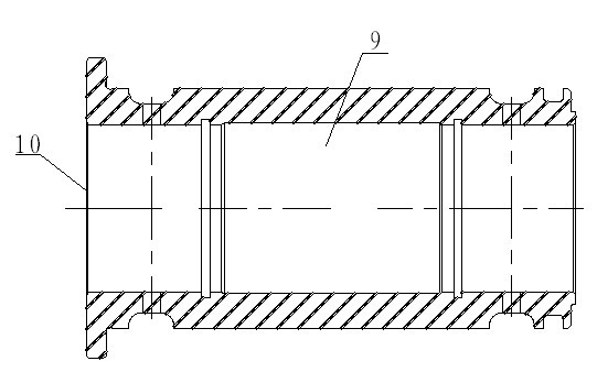
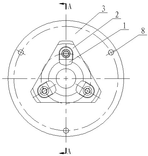
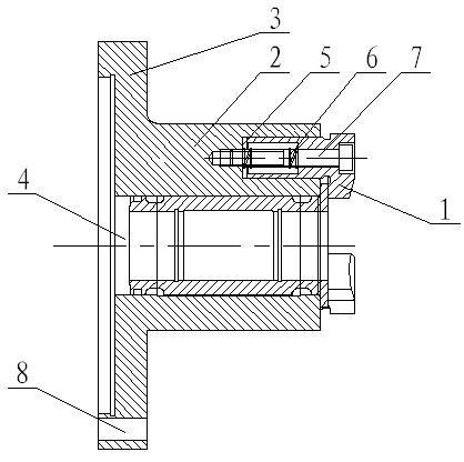
[0034] Embodiment 1: as figure 1 As shown, a turbocharger support bearing manufacturing method, the processing steps include: 1) rough turning the end surface and hole of the workpiece; 2) rough turning the other end surface and the outer circle; 3) annealing the workpiece to relieve stress ;4), finish turning end face and hole; 5), finish turning the other end face and hole; 6), milling semicircle positioning groove; 7) drilling radial holes at both ends; 8), milling outer circle flat square 9) fitter go burr; 12), oil wedge surface on milling thrust surface; 13), flaw detection inspection; 14), fitter deburring, cleaning parts; 15), comprehensive inspection; its characteristic is: between process 2) and process 4) Process 3), anneal the workpiece to relieve stress; use process 10) and process 11) between process 9) and process 12), in which process 10), use positioning tooling, use the tooling hole to locate the outer circle of the workpiece, and press the thrust of the work...


PUM


Abstract

The invention discloses a manufacturing method of a pedestal bearing for a turbocharger and a positioning tool for the same. The manufacturing method comprises the following machining procedures of: 1), roughly turning one end surface and a hole of a workpiece; 2), roughly turning the other end surface and an outer circle of the workpiece; 3), annealing the workpiece to remove stress; 4), carrying out finish turning on the end surface and the hole; 5), carrying out the finish turning on the other end surface and the hole; 6), milling a semicircular positioning groove; 7), drilling radial holes at two ends; 8), milling the flat and square parts of the outer circle; 9), removing burrs by a bench worker; 12), milling an oil applying wedge surface of a thrust surface; 13), carrying out flaw detection; 14), removing the burrs by the bench worker and cleaning a part; and 15), carrying out comprehensive detection. The procedure 3) is adopted between the procedure 2) and the procedure 4) to anneal the workpiece to remove the stress; a procedure 10) and a procedure 11) are adopted between the procedure 9) and the procedure 12); the procedure 10) comprises the following steps of: adopting the positioning tool, positioning the outer circle of the workpiece by utilizing a tool hole, compacting the thrust surface of the workpiece, and accurately grinding the holes; and the procedure 11) comprises the following steps of: positioning the holes by utilizing a taper shaft, and accurately grinding the outer circle and the thrust surface. The manufacturing method and the positioning tool have the advantages that the procedures are arranged reasonably, and the machining quality and the machining efficiency can be effectively improved.

Description

[0001] technical field [0002] The invention relates to a manufacturing method of a supporting bearing and a positioning tool thereof, in particular to a manufacturing method of a turbocharger supporting bearing and a positioning tool thereof. Background technique [0003] There are 15 processes in the existing turbocharger support bearing manufacturing method, which are: (1) casting annealing to relieve stress; (2) rough turning end face and hole; (3) rough turning the other end face and outer circle; ( 4) Finish turning end face and hole; (5) Finish turning the other end face and outer circle; (6) Milling semicircle positioning groove; (7) Drilling radial holes at both ends; (8) Milling outer circle flat square; (9) Deburring by fitter; (10) hard three-jaw clamp outer circle, fine grinding hole and thrust surface; (11) positioning hole with tapered mandrel, fine grinding outer circle; (12) milling oil wedge surface on thrust surface; (13) Flaw detection inspection; (...

Claims


Application Information

Patent Timeline
Patent Type & Authority Applications(China)
IPC IPC(8): B23P15/00B24B41/06
Inventor 段昌文罗兵胡亚
Owner CHONGQING JIANGJIN SHIPBUILDING IND
Why Eureka
Try Eureka