Copper recovery apparatus and copper recovery method

A recovery device and technology of copper hydroxide, applied in separation methods, separation devices, chemical instruments and methods, etc., can solve the problems of a lot of waste, low copper recovery efficiency, low copper purity, etc.

Inactive Publication Date: 2012-09-19
KK TOSHIBA
7 Cites 3 Cited by

AI-Extracted Technical Summary

Problems solved by technology

[0006] However, in the existing method, since the recovered copper precipitate/polymer aggregate itself contains a large amount of polymer, there is a problem that the copper purity per unit volume of the aggregate is low and the recovery...

Method used

[0074] In addition, in the case of an aggregate obtained by aggregating magnetic particles of a polymer-coated filter aid, it is preferable that the aggregate has a characteristic shape. That is, in the filter aid according to the present embodiment, when the average particle diameter of the magnetic particles is D1, the average aggregation diameter D2 of the aggregates satisfies D1

Abstract

According to one embodiment, a copper recovery apparatus includes a precipitation tank configured to make a drainage containing copper ions be alkalinity and precipitate copper hydroxide grains in water, a filter aid supplier for supplying an aid composed of magnetic particles or condensed matters and having an average diameter of 0.5 [mu]m to 20 [mu]m, a mixing tank configured to mix the filter aid with a water to produce a suspension, a solid-liquid separator(3) provided with a filter (33) of which the interior is divided into an upper space and a lower space, a suspension supplying line(L7,L2) configured to supply the suspension to the upper space of the separator from the precipitation tank and form a pre-coating layer composed of the aid on the filter, a processed water supplying lines (L2) making the processed water containing hydrogen copper oxide particles pass through the pre-coating layer and the filter via the separation tank and the solid-liquid separator to thereby capture the hydrogen copper oxide particles on the pre-coating layer and supply filtering liquid to the lower space; a peeling water supplying lines (L31,L11) for supplying a peeling water used for peeling the pre-coating layer from the filter to the upper space of the solid-liquid separator; a separation tank (4) configured to receive the detached matter of the pre-coating layer discharged together with the detaching water from the separator to magnetically separate copper hydroxide grains and filter aid, a copper recovery line (L8) configure to discharge and recover the detaching water containing the hydrogen copper oxide particles from the separation tank, and an aid returning line (L5) configured to return the separated filter aid to the filter aid supplier from the separation tank.

Application Domain

Water contaminantsTreatment involving filtration +5

Technology Topic

IonPrecipitation +11

Image

  • Copper recovery apparatus and copper recovery method
  • Copper recovery apparatus and copper recovery method
  • Copper recovery apparatus and copper recovery method

Examples

  • Experimental program(9)
  • Comparison scheme(1)

Example

[0098] (third embodiment)
[0099] refer to Image 6 The 3rd copper recovery apparatus 1B used for the precoating method is demonstrated. In addition, this embodiment omits the description of the part which overlaps with the above-mentioned embodiment.
[0100] In the copper recovery device 1B of the third embodiment, the cleaning water supply line L10 and the stripping water supply line L11 , which are two lines for supplying tap water, are respectively connected to the upper space 31 of the solid-liquid separator 3B. The cleaning water supply line L10 is connected to the upper space 31 of the solid-liquid separator 3B, supplies tap water to the upper space 31 , and removes ionic components in the copper compound contained in the deposit layer on the filter 33 . By introducing abundant tap water into the upper space 31 of the solid-liquid separator through the cleaning water supply line L10, cationic components (Na ions, Ca ions, Mg ions, etc.) contained in the precoat layer can be effectively removed.
[0101]The stripping water supply line L11 is connected to the side of the upper space 31 of the solid-liquid separator 3B, and supplies tap water from the side to the upper space 31 to peel and remove the precoat layer from the filter 33 . Tap water with sufficient water volume and pressure is introduced from the side to the upper space 31 of the solid-liquid separator 3B through the stripping water supply line L11, and the pressure of the water can strip the precoat layer from the filter 33 and decompose it into pieces. In this case, a spray nozzle is attached to the connecting portion of the stripping water supply line L11 and the solid-liquid separator 3B, and if water is sprayed rapidly from the nozzle, the stripping effect of the precoat layer is improved, and the decomposition efficiency is further improved.
[0102] (Example)
[0103] Hereinafter, it demonstrates in more detail using an Example.
[0104] [Preparation of filter aid]
[0105] The following six filter aids A to F were prepared as filter aids used in the above-mentioned water treatment method.
[0106] (filter aid A)
[0107] Magnetite particles (average particle diameter: 2 μm) were prepared.
[0108] (Filter Aid B)
[0109] Magnetite particles (average particle diameter: 0.5 μm) were prepared.
[0110] (filter aid C)
[0111] Magnetite particles (average particle diameter: 5 μm) were prepared.
[0112] (filter aid D)
[0113] A composition was obtained by dissolving 30 parts by weight of polymethyl methacrylate in 3 liters of tetrahydrofuran to prepare a solution, and dispersing 300 parts by weight of magnetite particles having an average particle diameter D1 of 2 μm in the solution. This composition was slowly sprayed using a small spray dryer (Shibata Scientific Co., Ltd., B-290 type) to prepare a filter aid having an average aggregation diameter (average secondary particle diameter) D2 of about 11 μm in spherical aggregation. The average coating thickness t was 0.038 μm.
[0114] (Filter Aid E)
[0115] A composition was obtained by dissolving 30 parts by weight of polymethyl methacrylate in 3 liters of tetrahydrofuran to prepare a solution, and dispersing 300 parts by weight of magnetite particles having an average particle diameter of 2 μm (A) in the solution. This composition was slowly sprayed using a small spray dryer (B-290 type, manufactured by Shibata Scientific Co., Ltd.), to prepare a filter aid having an aggregated spherical average secondary particle diameter D2 of about 18 μm. The average coating thickness t was 0.038 μm (C).
[0116] (Filter Aid F)
[0117] 40 parts by weight of resole phenolic resin was dissolved in 3 liters of water to make a solution, and in this solution, 300 parts by weight of magnetite particles (specific surface area 2.5 m) were dispersed with an average particle diameter of 2 μm (A). 2 /g) to obtain a composition. This composition was slowly sprayed using a small spray dryer (B-290 type, manufactured by Shibata Scientific Co., Ltd.), to prepare a filter aid having an aggregated spherical average secondary particle diameter D2 of about 11 μm. The average coating thickness calculated from the density of polymerized phenolic resin and the specific surface area of ​​magnetite was 0.044 μm (C).

Example Embodiment

[0118] (Example 1)
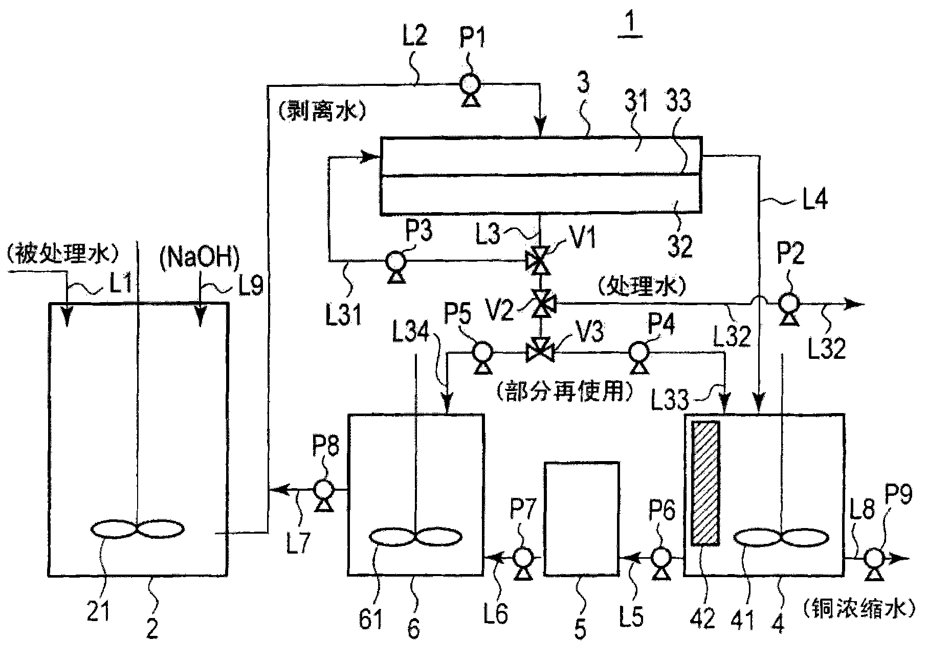
[0119] made as figure 1 Apparatus 1 shown roughly. Water to be treated containing copper is supplied to the precipitation tank 2, and an aqueous sodium hydroxide solution (indicated as NaOH in the figure) is added to the precipitation tank to make it alkaline and copper hydroxide is deposited. In addition, the filter aid is sent from the filter aid tank 5 to the mixing tank 6, and is mixed with a part of the reused treated water to prepare a filter aid slurry. First, the filter aid slurry is sent to the upper space 31 of the solid-liquid separation device 3 to form a filter aid film on the filter 33 . Thereafter, the liquid to be treated obtained by precipitating copper is supplied under pressure to the solid-liquid separation device 3 , and solid-liquid separation (filtration) is performed by passing through a membrane of a filter aid formed in advance. The filtrate is a weakly alkaline treatment liquid from which copper has been removed, and it can be drained through a neutralization tank, but it is also possible to use the filtrate as stripping water for the sediment layer to be peeled off from the filter 33 of the solid-liquid separation device, or as stripping water from the separation tank. The electromagnet 42 of the tank flushes the cleaning water of the filter aid, or serves as the dilution solvent when the filter aid slurry of the mixing tank 6 is made. When the filtration of the water to be treated is completed, a filter aid and a filter cake of deposited copper compound particles are present on the filter 33 in the solid-liquid separator 3 . In order to wash it, washing water is supplied from the side of the filter 33 to pulverize the filter cake, and the filter cake is supplied to the separation tank 4 . The separation tank 4 is equipped with a stirring screw 41 and an electromagnet 42 (magnetic separation mechanism), and separates the filter aid and copper compound particles while mixing, and collects and separates only the filter aid with a magnet. The liquid in which the filter aid is recovered is recovered as copper concentrated water containing high-concentration copper compound particles, washed with the supplied cleaning water, and returned to the filter aid tank 5 . The filter aid returned in this way is supplied to the mixing tank 6 and reused.
[0120] As water to be treated, an aqueous solution of copper sulfate containing 50 mg/L in terms of copper was prepared. This was supplied to the precipitation tank 2, and 48% sodium hydroxide was added dropwise, and pH was adjusted to 10. After mixing for a while, it was confirmed that a mixed salt (copper) compound of copper hydroxide and copper sulfate mainly composed of light green copper hydroxide precipitated.
[0121] Moreover, the filter aid was supplied from the filter aid tank 5 filled with the filter aid A to the mixing tank 6, and water was mixed, and the filter aid slurry was produced. This was supplied to the solid-liquid separator 3 , and a filter aid layer having an average thickness of 1 mm was produced on the filter 33 . Thereafter, after the water to be treated was supplied from the precipitation tank 2 to the solid-liquid separator 3 and filtered, it was confirmed that 99% or more of copper in the filtered water (treated water) was recovered. After the filtration treatment, washing water is supplied from the side of the filter 33 of the solid-liquid separator 3 , and the layer formed on the filter 33 is broken and supplied to the separation tank 4 . After the agitator in the separation tank 4 was operated to separate the filter aid and the copper compound, the electromagnet 42 was operated to separate only the filter aid, and the liquid was discharged to obtain a copper concentrate. As a result of analyzing the copper concentrate, it was confirmed that the main component of the slurry was a mixed salt of copper hydroxide and copper sulfate, which mainly consisted of copper hydroxide. Thereafter, the magnetic field of the electromagnet 42 is released, and the washing water is supplied to make a filter aid slurry, which is returned to the filter aid tank 5 . Thereafter, it is supplied to the mixing tank 6 and can be reused without any problem by performing the same operation.

Example Embodiment

[0122] (Example 2)
[0123] Using the same apparatus as in Example 1, except that the filter aid B was used instead of the filter aid A, the test was carried out in the same manner. The recovery rate of copper is above 99%. Compared with Example 1, the flow rate of the solid-liquid separation device became half, but still operated without problems.

PUM

PropertyMeasurementUnit
The average particle size2.0µm
The average particle size0.5µm
The average particle size5.0µm

Description & Claims & Application Information

We can also present the details of the Description, Claims and Application information to help users get a comprehensive understanding of the technical details of the patent, such as background art, summary of invention, brief description of drawings, description of embodiments, and other original content. On the other hand, users can also determine the specific scope of protection of the technology through the list of claims; as well as understand the changes in the life cycle of the technology with the presentation of the patent timeline. Login to view more.
Why Eureka
Try Eureka